Installation
Wiring to Power Supply
Figure 10 |
WARNING!
ELECTRICALGROUNDINGINSTRUCTIONS
THISAPPLIANCEISFITTEDWITHANELECTRICAL JUNCTIONBOXWITH 3 WIRES, ONE OF WHICH (GREEN/YELLOW) SERVES TO GROUND THE APPLIANCE. TO PROTECT YOU AGAINST ELECTRIC SHOCK, THE GREENANDYELLOWWIREMUSTBECONNECTEDTOTHEGROUNDING WIRE IN YOUR
HOMEELECTRICALSYSTEM,ANDITMUSTUNDERNOCIRCUMSTANCES BE CUT OR REMOVED.
Warning:Turnoffpowercircuitattheservicepanelbeforewiringthisunit. 120 VAC, 15 or 20 Amp circuit required.
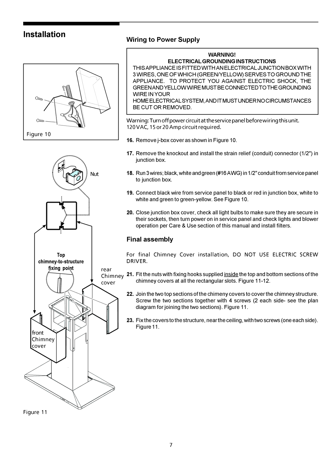
16.Remove
| 17. | Remove the knockout and install the strain relief (conduit) connector (1/2") in |
|
| junction box. |
Nut | 18. | Run 3 wires; black, white and green (#16 AWG) in 1/2" conduit from service panel |
|
| to junction box. |
Top
fixing point
front Chimney cover
Figure 11
| 19. | Connect black wire from service panel to black or red in junction box, white to |
|
| white and green to |
| 20. | Close junction box cover, check all light bulbs to make sure they are secure in |
|
| their sockets, then turn power on in service panel and check lights and blower |
|
| operation per Care & Use section of this manual and install filters. |
| Final assembly | |
| For final Chimney Cover installation, DO NOT USE ELECTRIC SCREW | |
| DRIVER. | |
rear | 21. | Fit the nuts with fixing hooks supplied inside the top and bottom sections of the |
Chimney | ||
cover |
| chimney covers at all the rectangular slots. Figure |
|
| |
| 22. | Join the two top sections of the chimeny covers to cover the chimney structure. |
|
| Screw the two sections together with 4 screws (2 each side- see the plan |
|
| diagram for joining the two sections). Figure 11. |
| 23. | Fix the covers to the structure, near the ceiling, with two screws (one each side). |
|
| Figure 11. |
7
