WIRING ELECTRONIC SPARK IGNITIONS

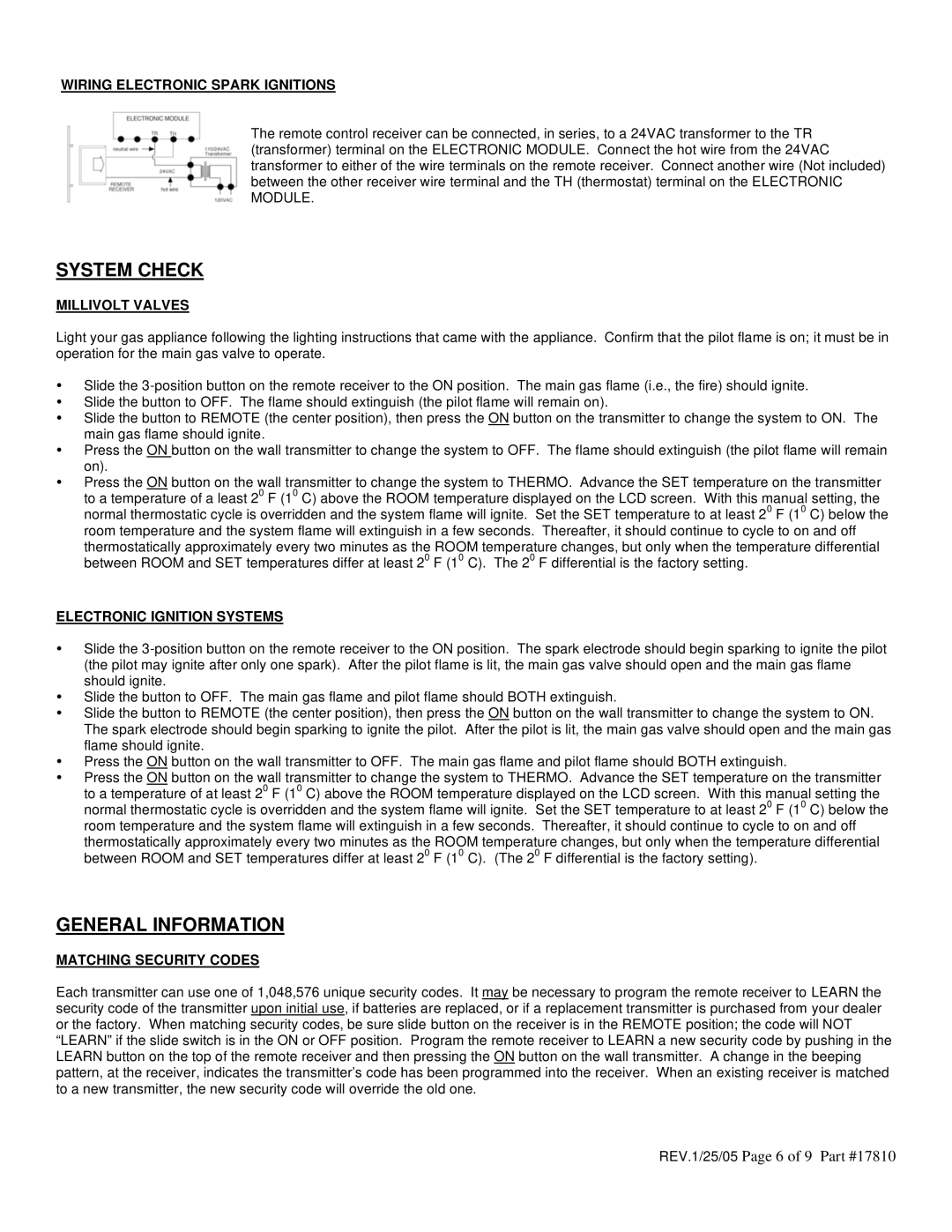
The remote control receiver can be connected, in series, to a 24VAC transformer to the TR (transformer) terminal on the ELECTRONIC MODULE. Connect the hot wire from the 24VAC transformer to either of the wire terminals on the remote receiver. Connect another wire (Not included) between the other receiver wire terminal and the TH (thermostat) terminal on the ELECTRONIC MODULE.

SYSTEM CHECK

MILLIVOLT VALVES

Light your gas appliance following the lighting instructions that came with the appliance. Confirm that the pilot flame is on; it must be in operation for the main gas valve to operate.

Slide the 3-position button on the remote receiver to the ON position. The main gas flame (i.e., the fire) should ignite.

Slide the button to OFF. The flame should extinguish (the pilot flame will remain on).

Slide the button to REMOTE (the center position), then press the ON button on the transmitter to change the system to ON. The main gas flame should ignite.

Press the ON button on the wall transmitter to change the system to OFF. The flame should extinguish (the pilot flame will remain on).

Press the ON button on the wall transmitter to change the system to THERMO. Advance the SET temperature on the transmitter to a temperature of a least 20 F (10 C) above the ROOM temperature displayed on the LCD screen. With this manual setting, the normal thermostatic cycle is overridden and the system flame will ignite. Set the SET temperature to at least 20 F (10 C) below the room temperature and the system flame will extinguish in a few seconds. Thereafter, it should continue to cycle to on and off

thermostatically approximately every two minutes as the ROOM temperature changes, but only when the temperature differential between ROOM and SET temperatures differ at least 20 F (10 C). The 20 F differential is the factory setting.

ELECTRONIC IGNITION SYSTEMS

Slide the 3-position button on the remote receiver to the ON position. The spark electrode should begin sparking to ignite the pilot (the pilot may ignite after only one spark). After the pilot flame is lit, the main gas valve should open and the main gas flame should ignite.

Slide the button to OFF. The main gas flame and pilot flame should BOTH extinguish.

Slide the button to REMOTE (the center position), then press the ON button on the wall transmitter to change the system to ON. The spark electrode should begin sparking to ignite the pilot. After the pilot is lit, the main gas valve should open and the main gas flame should ignite.

Press the ON button on the wall transmitter to OFF. The main gas flame and pilot flame should BOTH extinguish.

Press the ON button on the wall transmitter to change the system to THERMO. Advance the SET temperature on the transmitter to a temperature of at least 20 F (10 C) above the ROOM temperature displayed on the LCD screen. With this manual setting the normal thermostatic cycle is overridden and the system flame will ignite. Set the SET temperature to at least 20 F (10 C) below the room temperature and the system flame will extinguish in a few seconds. Thereafter, it should continue to cycle to on and off

thermostatically approximately every two minutes as the ROOM temperature changes, but only when the temperature differential between ROOM and SET temperatures differ at least 20 F (10 C). (The 20 F differential is the factory setting).

GENERAL INFORMATION

MATCHING SECURITY CODES

Each transmitter can use one of 1,048,576 unique security codes. It may be necessary to program the remote receiver to LEARN the security code of the transmitter upon initial use, if batteries are replaced, or if a replacement transmitter is purchased from your dealer or the factory. When matching security codes, be sure slide button on the receiver is in the REMOTE position; the code will NOT “LEARN” if the slide switch is in the ON or OFF position. Program the remote receiver to LEARN a new security code by pushing in the LEARN button on the top of the remote receiver and then pressing the ON button on the wall transmitter. A change in the beeping pattern, at the receiver, indicates the transmitter’s code has been programmed into the receiver. When an existing receiver is matched to a new transmitter, the new security code will override the old one.

REV.1/25/05 Page 6 of 9 Part #17810

Page 6
Image 6
Elitegroup TRW-1 installation instructions System Check, REV.1/25/05 Page 6 of 9

TRW-1 specifications

The Elitegroup TRW-1 is a pioneering solution in the realm of gaming and content creation, designed to cater to the demands of modern users who prioritize performance and reliability. This advanced motherboard has garnered attention for its cutting-edge features and robust technologies, making it a preferred choice for both enthusiasts and professionals.

One of the defining features of the TRW-1 is its comprehensive support for the latest Intel processors, ensuring compatibility with a wide range of powerful CPUs. This flexibility allows users to harness the full potential of the latest multi-core technology, which is particularly beneficial for demanding tasks such as gaming, video editing, and 3D rendering.

The TRW-1 is equipped with a state-of-the-art power delivery system, featuring high-quality capacitors and multiple phases dedicated to CPU power. This design ensures stable voltage and enhanced efficiency, allowing for better performance even under heavy loads. Additionally, the motherboard is designed with improved thermal management solutions, including heatsinks and strategically placed fan headers, which help maintain optimal temperatures during intense usage.

Connectivity is another highlight of the Elitegroup TRW-1, as it includes support for the latest PCIe 4.0 standard. This feature allows for lightning-fast data transfer speeds with modern graphics cards and SSDs, further elevating gaming experiences and productivity levels. The TRW-1 also supports high-speed DDR4 memory, with multiple DIMM slots accommodating substantial amounts of RAM, which is essential for multitasking and resource-heavy applications.

In terms of expansion, the TRW-1 features a well-designed layout that includes multiple PCIe slots for additional expansion cards, making it easy for users to enhance their systems with additional GPUs, sound cards, or networking capabilities.

For storage, the TRW-1 supports numerous SATA and M.2 slots, giving users the flexibility to configure their storage according to their specific needs. The inclusion of advanced storage technologies, such as RAID support, ensures data redundancy and improved performance.

Overall, the Elitegroup TRW-1 stands out in the crowded motherboard market by combining leading-edge technologies, excellent performance characteristics, and user-friendly features. Its balance of power, connectivity options, and expandability make it a compelling choice for anyone looking to build a high-performance PC. Whether for gaming, content creation, or professional applications, the TRW-1 delivers a reliable and robust platform that meets the needs of today’s users.