MULTI-STAGE TERMINAL OUTPUTS
Refer to equipment manufacturers’ instructions for specific system wiring information.
You can configure the thermostat for use with either
This thermostat is designed to operate a
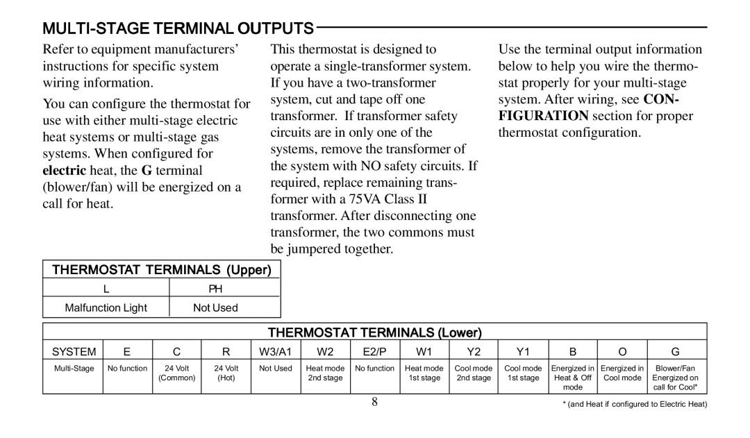
Use the terminal output information below to help you wire the thermo- stat properly for your
THERMOSTAT TERMINALS (Upper) |
|
|
|
|
|
|
|
|
| |||||
| L |
|
| PH |
|
|
|
|
|
|
|
|
|
|
Malfunction Light |
| Not Used |
|
|
|
|
|
|
|
|
|
| ||
|
|
|
|
|
|
|
|
|
|
|
|
|
|
|
|
|
|
|
|
|
|
|
|
|
|
|
|
| |
|
|
|
|
| THERMOSTAT TERMINALS (Lower) |
|
|
|
| |||||
SYSTEM | E |
| C | R | W3/A1 | W2 | E2/P | W1 | Y2 | Y1 | B | O | G | |
No function | 24 Volt | 24 Volt | Not Used | Heat mode | No function | Heat mode | Cool mode | Cool mode | Energized in | Energized in | Blower/Fan | |||
|
| (Common) | (Hot) |
|
| 2nd stage |
| 1st stage | 2nd stage | 1st stage | Heat & Off | Cool mode | Energized on | |
|
|
|
|
|
|
|
|
|
|
|
| mode |
| call for Cool* |
|
|
|
|
|
|
|
|
|
|
|
|
|
|
|
8 | * (and Heat if configured to Electric Heat) |