EMERSON BLUE 12”
TOUCHSCREEN THERMOSTATS
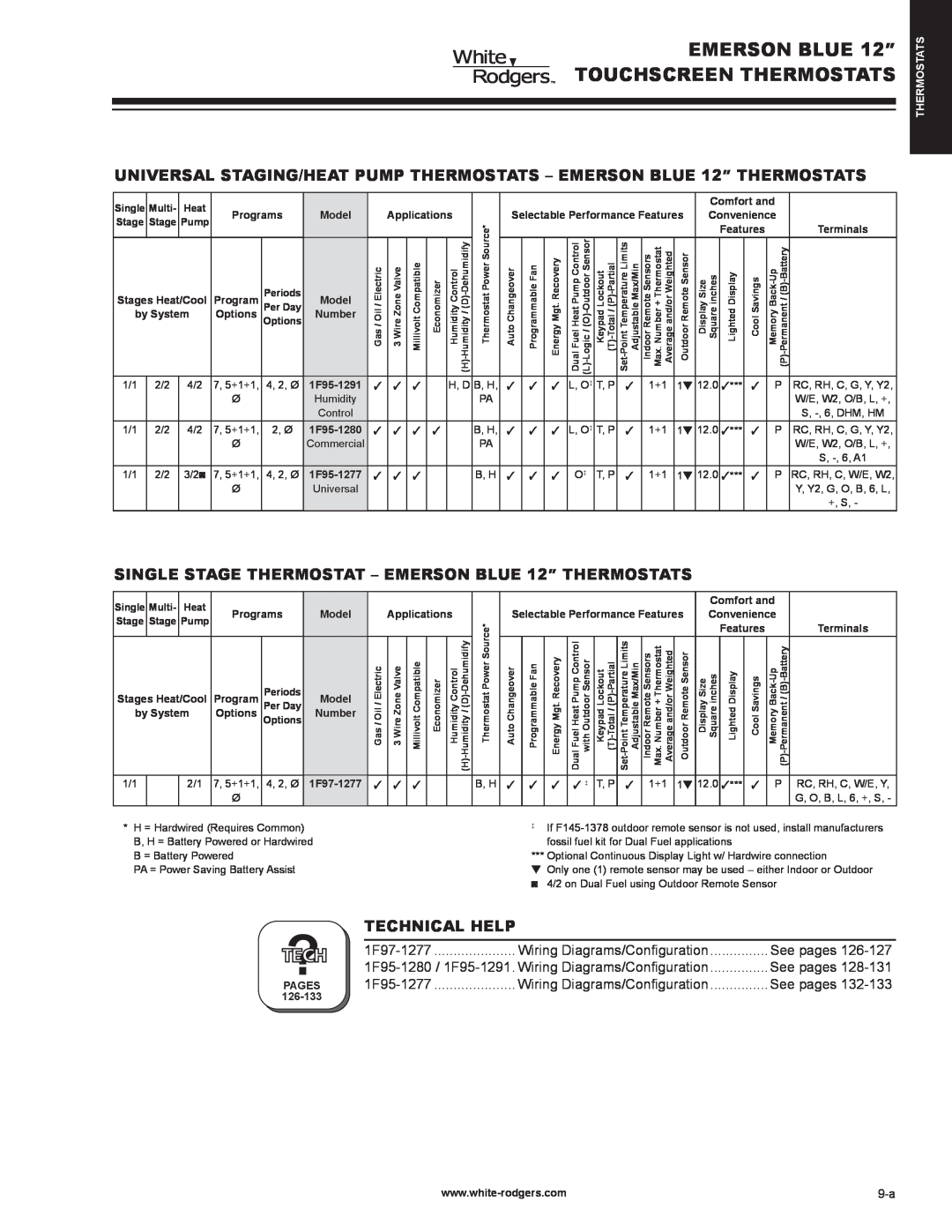
UNIVERSAL STAGING/HEAT PUMP THERMOSTATS – EMERSON BLUE 12” THERMOSTATS
Single | Multi- | Heat |
|
|
|
|
|
|
|
|
|
|
|
|
|
|
|
|
| Comfort and |
| |||
Programs | Model |
| Applications |
| Selectable Performance Features | Convenience |
| |||||||||||||||||
Stage | Stage | Pump |
| ThermostatPower Source* |
| |||||||||||||||||||
|
|
|
|
|
|
|
|
|
|
|
|
|
|
|
|
| Features |
| Terminals | |||||
|
|
|
|
|
|
|
|
|
|
|
|
|
|
|
|
|
|
|
|
| ||||
Stages Heat/Cool | Program | Periods | Model | Electric/Oil/Gas | ZoneWire3Valve | CompatibleMillivolt | Economizer | ControlHumidity | ChangeoverAuto | ProgrammableFan | RecoveryMgt.Energy | PumpHeatFuelDualControl | LockoutKeypad | RemoteIndoorSensors Thermostat+NumberMax. and/orAverageWeighted | RemoteOutdoorSensor | SizeDisplay inchesSquare | DisplayLighted | SavingsCool |
| |||||
|
|
|
|
|
|
|
|
|
|
|
|
|
|
|
|
|
|
| ||||||
Per Day |
|
|
|
|
|
|
|
|
|
|
|
|
|
|
|
|
|
|
| |||||
by System | Options | Options | Number |
|
|
|
|
|
|
|
|
|
|
|
|
|
|
|
|
|
|
| ||
|
|
|
|
|
|
|
|
|
|
|
|
|
|
|
|
|
|
|
|
|
|
|
|
|
1/1 | 2/2 | 4/2 | 7, 5+1+1, | 4, 2, Ø | 3 | 3 | 3 |
| H, D | B, H, | 3 | 3 | 3 | L, O‡ | T, P | 3 | 1+1 | 1t | 12.0 | 3*** | 3 | P | RC, RH, C, G, Y, Y2, | |
|
|
| Ø |
| Humidity |
|
|
|
|
| PA |
|
|
|
|
|
|
|
|
|
|
|
| W/E, W2, O/B, L, +, |
|
|
|
|
| Control |
|
|
|
|
|
|
|
|
|
|
|
|
|
|
|
|
|
| S, |
1/1 | 2/2 | 4/2 | 7, 5+1+1, | 2, Ø | 3 | 3 | 3 | 3 |
| B, H, | 3 | 3 | 3 | L, O‡ | T, P | 3 | 1+1 | 1t | 12.0 | 3*** | 3 | P | RC, RH, C, G, Y, Y2, | |
|
|
| Ø |
| Commercial |
|
|
|
|
| PA |
|
|
|
|
|
|
|
|
|
|
|
| W/E, W2, O/B, L, +, |
|
|
|
|
|
|
|
|
|
|
|
|
|
|
|
|
|
|
|
|
|
|
|
| S, |
1/1 | 2/2 | 3/2◙ | 7, 5+1+1, | 4, 2, Ø | 3 | 3 | 3 |
|
| B, H | 3 | 3 | 3 | O‡ | T, P | 3 | 1+1 | 1t | 12.0 | 3*** | 3 | P | RC, RH, C, W/E, W2, | |
|
|
| Ø |
| Universal |
|
|
|
|
|
|
|
|
|
|
|
|
|
|
|
|
|
| Y, Y2, G, O, B, 6, L, |
|
|
|
|
|
|
|
|
|
|
|
|
|
|
|
|
|
|
|
|
|
|
|
| +, S, - |
THERMOSTATS
SINGLE STAGE THERMOSTAT – EMERSON BLUE 12” THERMOSTATS
Single | Multi- | Heat | Programs | Model | ||
Stage | Stage | Pump | ||||
|
|
| ||||
|
|
|
| Periods |
| |
Stages Heat/Cool | Program | Model | ||||
Per Day | ||||||
by System | Options | Options | Number | |||
1/1 |
|
| 7, 5+1+1, | 4, 2, Ø | ||
| 2/1 | |||||
|
|
| Ø |
|
| |
| Applications | Thermostat Power Source* | |||||||
Gas / Oil / Electric |
| 3 Wire Zone Valve |
| Millivolt Compatible |
| Economizer |
| Humidity Control Humidity / | |
|
|
|
| ||||||
|
|
|
|
|
|
|
| (H)- |
|
3 |
| 3 |
| 3 |
|
|
|
| B, H |
|
|
|
|
|
|
|
|
|
|
|
|
|
|
|
|
|
| Comfort and |
| |||
Selectable Performance Features | Convenience |
| ||||||||||
|
|
|
|
|
|
|
|
| Features |
| Terminals | |
Auto Changeover | Programmable Fan | Energy Mgt. Recovery | Dual Fuel Heat Pump Control with Outdoor Sensor | Keypad Lockout | Indoor Remote Sensors Max. Number + Thermostat Average and/or Weighted | Outdoor Remote Sensor | Display Size Square inches | Lighted Display | Cool Savings | Memory |
| |
3 | 3 | 3 | 3 ‡ | T, P | 3 | 1+1 | 1t | 12.0 | 3*** | 3 | P | RC, RH, C, W/E, Y, |
|
|
|
|
|
|
|
|
|
|
|
| G, O, B, L, 6, +, S, - |
* H = Hardwired (Requires Common) | ‡ | If |
B, H = Battery Powered or Hardwired |
| fossil fuel kit for Dual Fuel applications |
B = Battery Powered | *** Optional Continuous Display Light w/ Hardwire connection | |
PA = Power Saving Battery Assist | t Only one (1) remote sensor may be used – either Indoor or Outdoor | |
| ◙ 4/2 on Dual Fuel using Outdoor Remote Sensor | |
TECHNICAL HELP
|
|
|
|
|
|
|
|
|
|
|
|
|
|
|
|
| Wiring. | ................Diagrams/Configuration | See pages | |
? |
|
|
|
|
| See pages | ||||||||||||||
|
|
| Wiring. | Diagrams/Configuration | See pages | |||||||||||||||
pages |
|
|
|
|
|
|
| |||||||||||||
|
|
|
|
|
|
| ||||||||||||||