BOOK 0958-B
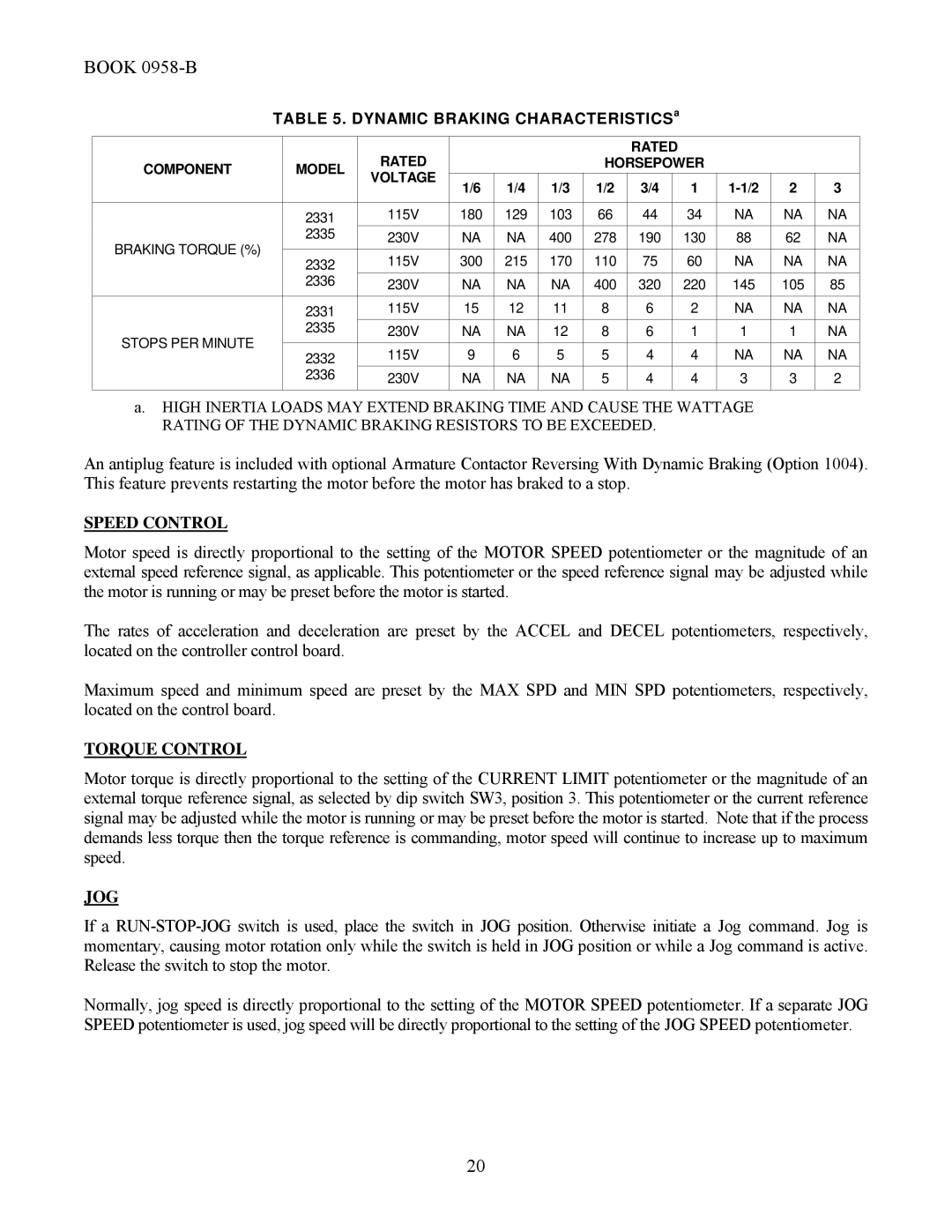
TABLE 5. DYNAMIC BRAKING CHARACTERISTICSa
|
| RATED |
|
|
|
| RATED |
|
|
|
| |
COMPONENT | MODEL |
|
|
| HORSEPOWER |
|
|
| ||||
VOLTAGE |
|
|
|
|
|
|
|
|
|
| ||
1/6 | 1/4 | 1/3 | 1/2 | 3/4 |
| 1 | 2 | 3 | ||||
|
|
| ||||||||||
|
|
|
| |||||||||
|
|
|
|
|
|
|
|
|
|
|
|
|
| 2331 | 115V | 180 | 129 | 103 | 66 | 44 |
| 34 | NA | NA | NA |
BRAKING TORQUE (%) | 2335 | 230V | NA | NA | 400 | 278 | 190 |
| 130 | 88 | 62 | NA |
2332 | 115V | 300 | 215 | 170 | 110 | 75 |
| 60 | NA | NA | NA | |
|
| |||||||||||
| 2336 | 230V | NA | NA | NA | 400 | 320 |
| 220 | 145 | 105 | 85 |
|
|
|
|
|
|
|
|
|
|
|
|
|
| 2331 | 115V | 15 | 12 | 11 | 8 | 6 |
| 2 | NA | NA | NA |
STOPS PER MINUTE | 2335 | 230V | NA | NA | 12 | 8 | 6 |
| 1 | 1 | 1 | NA |
|
|
|
|
|
|
|
|
|
|
|
| |
2332 | 115V | 9 | 6 | 5 | 5 | 4 |
| 4 | NA | NA | NA | |
|
| |||||||||||
| 2336 | 230V | NA | NA | NA | 5 | 4 |
| 4 | 3 | 3 | 2 |
|
|
|
|
|
|
|
|
|
|
|
|
|
a.HIGH INERTIA LOADS MAY EXTEND BRAKING TIME AND CAUSE THE WATTAGE RATING OF THE DYNAMIC BRAKING RESISTORS TO BE EXCEEDED.
An antiplug feature is included with optional Armature Contactor Reversing With Dynamic Braking (Option 1004). This feature prevents restarting the motor before the motor has braked to a stop.
SPEED CONTROL
Motor speed is directly proportional to the setting of the MOTOR SPEED potentiometer or the magnitude of an external speed reference signal, as applicable. This potentiometer or the speed reference signal may be adjusted while the motor is running or may be preset before the motor is started.
The rates of acceleration and deceleration are preset by the ACCEL and DECEL potentiometers, respectively, located on the controller control board.
Maximum speed and minimum speed are preset by the MAX SPD and MIN SPD potentiometers, respectively, located on the control board.
TORQUE CONTROL
Motor torque is directly proportional to the setting of the CURRENT LIMIT potentiometer or the magnitude of an external torque reference signal, as selected by dip switch SW3, position 3. This potentiometer or the current reference signal may be adjusted while the motor is running or may be preset before the motor is started. Note that if the process demands less torque then the torque reference is commanding, motor speed will continue to increase up to maximum speed.
JOG
If a
Normally, jog speed is directly proportional to the setting of the MOTOR SPEED potentiometer. If a separate JOG SPEED potentiometer is used, jog speed will be directly proportional to the setting of the JOG SPEED potentiometer.
20
