MODEL 381pH/ORP
3.4PREAMPLIFIER TROUBLESHOOTING. To deter- mine if the preamplifier is operable, proceed as follows:
1. | Remove the sensor from process. |
2. | Remove the cover from the body by grasping the |
SECTION 3.0
MAINTENANCE
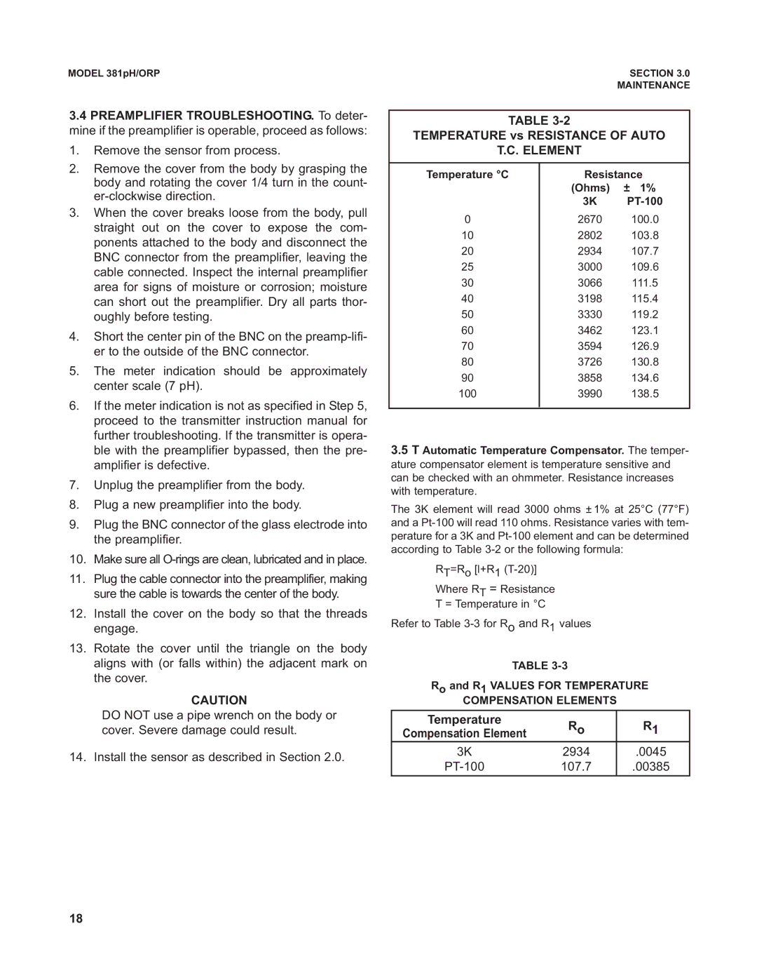
TABLE
TEMPERATURE vs RESISTANCE OF AUTO
T.C. ELEMENT
| body and rotating the cover 1/4 turn in the count- |
| |
3. | When the cover breaks loose from the body, pull |
| straight out on the cover to expose the com- |
| ponents attached to the body and disconnect the |
| BNC connector from the preamplifier, leaving the |
| cable connected. Inspect the internal preamplifier |
| area for signs of moisture or corrosion; moisture |
| can short out the preamplifier. Dry all parts thor- |
| oughly before testing. |
4. | Short the center pin of the BNC on the |
| er to the outside of the BNC connector. |
5. | The meter indication should be approximately |
| center scale (7 pH). |
6. | If the meter indication is not as specified in Step 5, |
| proceed to the transmitter instruction manual for |
| further troubleshooting. If the transmitter is opera- |
Temperature °C
0
10
20
25
30
40
50
60
70
80
90
100
Resistance
(Ohms) ± 1%
3K
2670 100.0
2802 103.8
2934 107.7
3000 109.6
3066 111.5
3198 115.4
3330 119.2
3462 123.1
3594 126.9
3726 130.8
3858 134.6
3990 138.5
| ble with the preamplifier bypassed, then the pre- |
| amplifier is defective. |
7. | Unplug the preamplifier from the body. |
8. | Plug a new preamplifier into the body. |
9. | Plug the BNC connector of the glass electrode into |
| the preamplifier. |
10. | Make sure all |
11. | Plug the cable connector into the preamplifier, making |
| sure the cable is towards the center of the body. |
12. | Install the cover on the body so that the threads |
| engage. |
13. | Rotate the cover until the triangle on the body |
| aligns with (or falls within) the adjacent mark on |
| the cover. |
CAUTION
DO NOT use a pipe wrench on the body or cover. Severe damage could result.
14. Install the sensor as described in Section 2.0.
3.5T Automatic Temperature Compensator. The temper- ature compensator element is temperature sensitive and can be checked with an ohmmeter. Resistance increases with temperature.
The 3K element will read 3000 ohms ± 1% at 25°C (77°F) and a
RT=Ro [l+R1
Where RT = Resistance
T = Temperature in °C
Refer to Table
TABLE
Ro and R1 VALUES FOR TEMPERATURE
COMPENSATION ELEMENTS
Temperature | Ro | R1 | |
Compensation Element | |||
|
| ||
|
|
| |
3K | 2934 | .0045 | |
107.7 | .00385 | ||
|
|
|
18