MODEL 396R pH/ORP | TABLE OF CONTENTS |
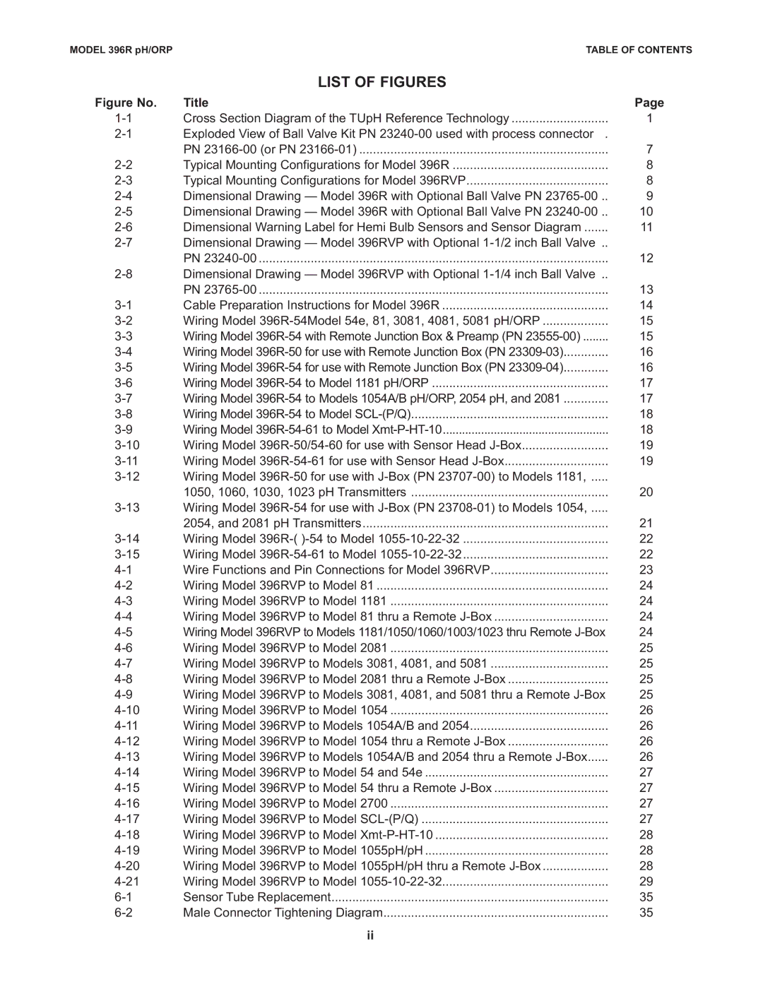
LIST OF FIGURES
Figure No. | Title | Page |
Cross Section Diagram of the TUpH Reference Technology | 1 | |
Exploded View of Ball Valve Kit PN |
| |
| PN | 7 |
Typical Mounting Configurations for Model 396R | 8 | |
Typical Mounting Configurations for Model 396RVP | 8 | |
Dimensional Drawing — Model 396R with Optional Ball Valve PN | 9 | |
Dimensional Drawing — Model 396R with Optional Ball Valve PN | 10 | |
Dimensional Warning Label for Hemi Bulb Sensors and Sensor Diagram | 11 | |
Dimensional Drawing — Model 396RVP with Optional |
| |
| PN | 12 |
Dimensional Drawing — Model 396RVP with Optional |
| |
| PN | 13 |
Cable Preparation Instructions for Model 396R | 14 | |
Wiring Model | 15 | |
Wiring Model | 15 | |
Wiring Model | 16 | |
Wiring Model | 16 | |
Wiring Model | 17 | |
Wiring Model | 17 | |
Wiring Model | 18 | |
Wiring Model | 18 | |
Wiring Model | 19 | |
Wiring Model | 19 | |
Wiring Model |
| |
| 1050, 1060, 1030, 1023 pH Transmitters | 20 |
Wiring Model |
| |
| 2054, and 2081 pH Transmitters | 21 |
Wiring Model 396R-( | 22 | |
Wiring Model | 22 | |
Wire Functions and Pin Connections for Model 396RVP | 23 | |
Wiring Model 396RVP to Model 81 | 24 | |
Wiring Model 396RVP to Model 1181 | 24 | |
Wiring Model 396RVP to Model 81 thru a Remote | 24 | |
Wiring Model 396RVP to Models 1181/1050/1060/1003/1023 thru Remote | 24 | |
Wiring Model 396RVP to Model 2081 | 25 | |
Wiring Model 396RVP to Models 3081, 4081, and 5081 | 25 | |
Wiring Model 396RVP to Model 2081 thru a Remote | 25 | |
Wiring Model 396RVP to Models 3081, 4081, and 5081 thru a Remote | 25 | |
Wiring Model 396RVP to Model 1054 | 26 | |
Wiring Model 396RVP to Models 1054A/B and 2054 | 26 | |
Wiring Model 396RVP to Model 1054 thru a Remote | 26 | |
Wiring Model 396RVP to Models 1054A/B and 2054 thru a Remote | 26 | |
Wiring Model 396RVP to Model 54 and 54e | 27 | |
Wiring Model 396RVP to Model 54 thru a Remote | 27 | |
Wiring Model 396RVP to Model 2700 | 27 | |
Wiring Model 396RVP to Model | 27 | |
Wiring Model 396RVP to Model | 28 | |
Wiring Model 396RVP to Model 1055pH/pH | 28 | |
Wiring Model 396RVP to Model 1055pH/pH thru a Remote | 28 | |
Wiring Model 396RVP to Model | 29 | |
Sensor Tube Replacement | 35 | |
Male Connector Tightening Diagram | 35 |
ii
