SECTION 2 SEQUENCE OF OPERATION
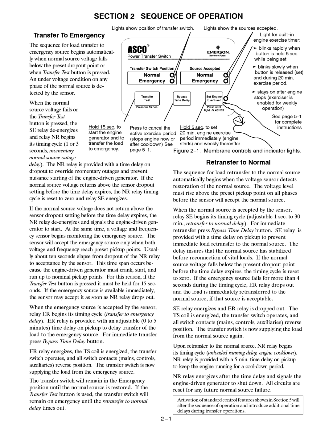
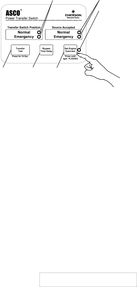
| Lights show position of transfer switch. | Lights show the sources accepted. | ||||
Transfer To Emergency |
|
|
|
| Light for | |
The sequence for load transfer to |
|
|
|
| engine exercise timer: | |
|
|
|
| ³ blinks rapidly when | ||
emergency source begins automatical- |
|
|
|
| ||
|
|
|
| button is held 5 sec. | ||
ly when normal source voltage falls |
|
|
|
| while being set | |
below the preset dropout point or |
|
|
|
| ³ blinks slowly when | |
when Transfer Test button is pressed. |
|
|
|
| button is released (set) | |
An under voltage condition on any |
|
|
|
| and during 20 min. | |
phase of the normal source is de- |
|
|
|
| exercise period. | |
|
|
|
| ³ stays on after engine | ||
tected by the sensor. |
|
|
|
|
| |
When the normal |
|
|
|
|
| stops (exerciser is |
|
|
|
|
| enabled for weekly | |
source voltage fails or |
|
|
|
|
| operation) |
the Transfer Test |
|
|
|
|
| See page |
button is pressed, the | Hold 15 sec. to | Press to cancel the |
| Hold 5 sec. to set | for complete | |
SE relay |
| instructions | ||||
start the engine | active exercise period | 20 min. engine exercise |
| |||
and relay NR begins |
| |||||
generator and to | (stops engine now or | period immediately (engine |
| |||
its timing cycle (1 or 3 | transfer the load | after cooldown) See |
| starts) and weekly thereafter. |
| |
seconds, momentary | to emergency. | page | Figure | |||
normal source outage |
|
|
|
| Retransfer to Normal | |
delay). The NR relay is provided with a time delay on |
|
| ||||
dropout to override momentary outages and prevent | The sequence for load retransfer to the normal source | |||||
nuisance starting of the | automatically begins when the voltage sensor detects | |||||
normal source voltage returns above the sensor dropout | restoration of the normal source. The voltage level | |||||
setting before the time delay expires, the NR relay timing | must rise above the preset pickup point on all phases | |||||
cycle is reset to zero and relay SE energizes. |
| before the sensor will accept the normal source. | ||||
If the normal source voltage does not return above the sensor dropout setting before the time delay expires, the NR relay
When the emergency source is accepted by the sensor, relay ER begins its timing cycle (transfer to emergency delay). ER relay is provided with an adjustable (0 to 5 minutes) time delay on pickup to delay transfer of the load to the emergency source. For immediate transfer press Bypass Time Delay button.
ER relay energizes, the TS coil is energized, the transfer switch operates, and all switch contacts (mains, controls, auxiliaries) reverse position. The transfer switch is now supplying the load from the emergency source.
The transfer switch will remain in the Emergency position until the normal source is restored. If the Transfer Test button is used, the transfer switch will remain on emergency until the retransfer to normal delay times out.
When the normal source is accepted by the sensor, relay SE begins its timing cycle (adjustable 1 sec. to 30 min., retransfer to normal delay). For immediate retransfer press Bypass Time Delay button. SE relay is provided with a time delay on pickup to prevent immediate load retransfer to the normal source. The delay insures that the normal source has stabilized before reconnection of vital loads. If the normal source voltage falls below the present dropout point before the time delay expires, the timing cycle is reset to zero. If the emergency source fails for more than 4 seconds during the timing cycle, ER relay drops out and the load is immediately retransferred to the normal source, if that source is acceptable.
SE relay energizes and ER relay is dropped out. The TS coil is energized, the transfer switch operates, and all switch contacts (mains, controls, auxiliaries) reverse position. The transfer switch is now supplying the load from the normal source again.
Upon retransfer to the normal source, NR relay begins its timing cycle (unloaded running delay, engine cooldown). NR relay is provided with a 5 min. time delay on pickup to keep the engine running for a
NR relay energizes after the time delay and signals the
Activation of standard control features shown in Section 5 will alter the sequence of operation and introduce additional time delays during transfer operations.