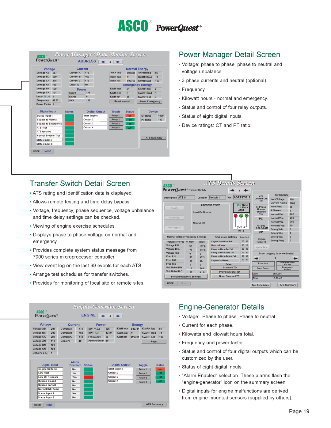
7000 specifications
The Emerson 7000 series is a versatile and advanced automation solution designed for modern industrial environments. Renowned for its reliability, scalability, and performance, the Emerson 7000 series is tailored to meet the complex demands of various industries, including oil and gas, chemical manufacturing, power generation, and food and beverage.At the heart of the Emerson 7000 series is its powerful and flexible architecture. This series integrates seamlessly with existing systems, allowing for easy upgrades without disrupting ongoing processes. The modular design enables users to customize their setups according to their specific needs, providing unmatched adaptability in dynamic operations.
One of the standout features of the Emerson 7000 is its intelligent diagnostics capabilities. This technology leverages advanced algorithms and machine learning to predict equipment failures and maintenance needs, thus minimizing unplanned downtime. By continuously monitoring critical parameters, the system provides operators with actionable insights, enhancing operational efficiency and safety.
The Emerson 7000 series also focuses on user-friendly interfaces. Its intuitive design allows operators to quickly navigate complex data and analytics, facilitating quicker decision-making. The human-machine interface (HMI) provides a clear visual representation of processes, empowering users to manage operations effectively.
Another cutting-edge technology in the Emerson 7000 series is its cybersecurity measures. With the increasing threat of cyber-attacks in industrial environments, Emerson has prioritized the integration of robust security protocols. These features protect sensitive data and ensure the integrity of operations, safeguarding organizations from potential breaches.
Additionally, the Emerson 7000 series supports a wide range of communication protocols, making it compatible with various devices and systems. This interoperability allows for greater collaboration between different technologies within a facility, streamlining workflows and enhancing productivity.
Lastly, the Emerson 7000 emphasizes sustainability and energy efficiency. By providing insights into energy consumption and operational performance, the system helps organizations minimize their environmental impact and reduce operational costs.
In summary, the Emerson 7000 series stands out as a comprehensive automation solution that combines cutting-edge technologies, user-friendly interfaces, robust cybersecurity, and a commitment to sustainability. With its ability to adapt to diverse industrial needs and enhance operational efficiency, the Emerson 7000 continues to be a preferred choice for businesses seeking to navigate the complexities of modern manufacturing and process automation.

