BP7384 Camden, CF3600 2/18/09 2:57 PM Page 6
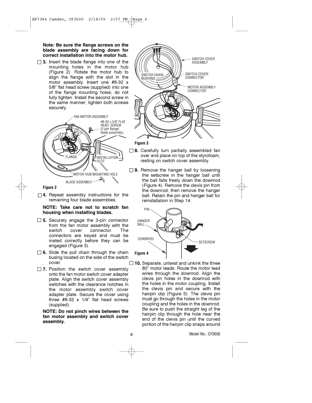
Note: Be sure the flange screws on the blade assembly are facing down for correct installation into the motor hub.
![]()
![]() 3. Insert the blade flange into one of the mounting holes in the motor hub (Figure 2). Rotate the motor hub to align the flange with the slot in the motor assembly. Insert one
3. Insert the blade flange into one of the mounting holes in the motor hub (Figure 2). Rotate the motor hub to align the flange with the slot in the motor assembly. Insert one
FAN MOTOR ASSEMBLY
![]() SWITCH COVER
SWITCH COVER
ASSEMBLY
SWITCH CHAIN | SWITCH COVER |
BUSHING | CONNECTOR |
![]() MOTOR ASSEMBLY
MOTOR ASSEMBLY
CONNECTOR
FLANGE
INSTALLATION SLOT
Figure 3
![]()
![]() 8. Carefully turn partially assembled fan over and place on top of the styrofoam, resting on switch cover assembly.
8. Carefully turn partially assembled fan over and place on top of the styrofoam, resting on switch cover assembly.
MOTOR HUB MOUNTING HOLE
BLADE ASSEMBLY ![]()
Figure 2
![]()
![]() 4. Repeat assembly instructions for the remaining four blade assemblies.
4. Repeat assembly instructions for the remaining four blade assemblies.
![]()
![]() 9. Remove the hanger ball by loosening the setscrew in the hanger ball until the ball falls freely down the downrod (Figure 4). Remove the clevis pin from the downrod, then remove the hanger ball. Retain the pin and hanger ball for reinstallation in Step 14.
9. Remove the hanger ball by loosening the setscrew in the hanger ball until the ball falls freely down the downrod (Figure 4). Remove the clevis pin from the downrod, then remove the hanger ball. Retain the pin and hanger ball for reinstallation in Step 14.
NOTE: Take care not to scratch fan housing when installing blades.
![]()
![]() 5. Securely engage the
5. Securely engage the
PIN
HANGER
BALL
DOWNROD
SETSCREW
![]()
![]() 6. Slide the pull chain through the chain busing located on the side of the switch cover.
6. Slide the pull chain through the chain busing located on the side of the switch cover.![]()
![]()
![]() 7. Position the switch cover assembly onto the fan motor switch cover adapter plate. Align the switch cover assembly switches with the clearance notches in the motor assembly switch cover adapter plate. Secure the cover using three
7. Position the switch cover assembly onto the fan motor switch cover adapter plate. Align the switch cover assembly switches with the clearance notches in the motor assembly switch cover adapter plate. Secure the cover using three
NOTE: Do not pinch wires between the fan motor assembly and switch cover assembly.
Figure 4
10.Separate, untwist and unkink the three 80” motor leads. Route the motor lead wires through the downrod. Align the clevis pin holes in the downrod with the holes in the motor coupling. Install the clevis pin and secure with the hairpin clip (Figure 5). The clevis pin must go through the holes in the motor coupling and the holes in the downrod. Be sure to push the straight leg of the hairpin clip through the hole near the end of the clevis pin until the curved portion of the hairpin clip snaps around
6 | Model No.: CF3600 |