CONNECTING TO A TV THAT HAS AN S-VIDEO INPUT JACK OR

COMPONENT VIDEO IN JACKS

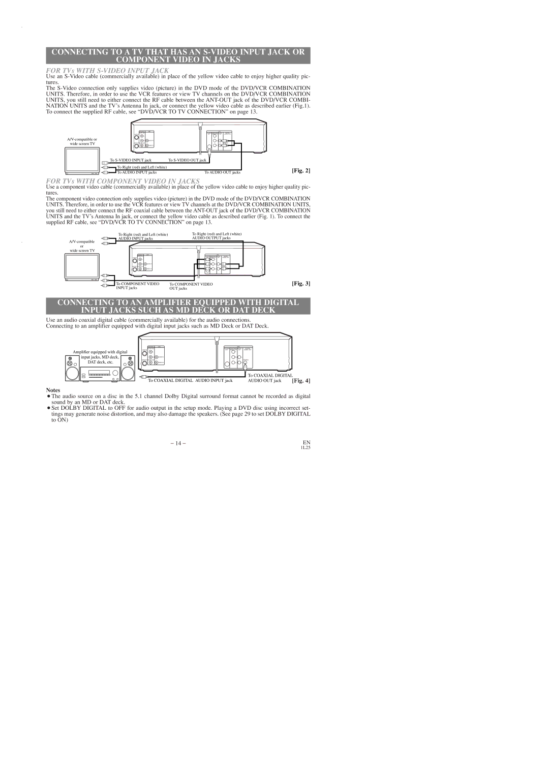
FOR TVs WITH S-VIDEO INPUT JACK

Use an S-Video cable (commercially available) in place of the yellow video cable to enjoy higher quality pic- tures.

The S-Video connection only supplies video (picture) in the DVD mode of the DVD/VCR COMBINATION UNITS. Therefore, in order to use the VCR features or view TV channels on the DVD/VCR COMBINATION UNITS, you still need to either connect the RF cable between the ANT-OUT jack of the DVD/VCR COMBI- NATION UNITS and the TV’s Antenna In jack, or connect the yellow video cable as described earlier (Fig.1). To connect the supplied RF cable, see “DVD/VCR TO TV CONNECTION” on page 13.

A/V-compatible or wide screen TV

DVD/VCR

VCR

DVD


AUDIO OUT


S-VIDEO COMPONENT AUDIO

DIGITAL

ANT-IN


OUT VIDEO OUT OUT

AUDIO OUT

L


Y


R

AUDIO IN

Cb

L

ANT-OUT VIDEO OUT


COAXIAL


VIDEO IN

Cr

R

To S-VIDEO INPUT jack

To S-VIDEO OUT jack


To Right (red) and Left (white)


To AUDIO INPUT jacks

To AUDIO OUT jacks

[Fig. 2]

FOR TVs WITH COMPONENT VIDEO IN JACKS

Use a component video cable (commercially available) in place of the yellow video cable to enjoy higher quality pic- tures.

The component video connection only supplies video (picture) in the DVD mode of the DVD/VCR COMBINATION UNITS. Therefore, in order to use the VCR features or view TV channels at the DVD/VCR COMBINATION UNITS, you still need to either connect the RF coaxial cable between the ANT-OUT jack of the DVD/VCR COMBINATION UNITS and the TV’s Antenna In jack, or connect the yellow video cable as described earlier (Fig. 1). To connect the supplied RF cable, see “DVD/VCR TO TV CONNECTION” on page 13.

A/V-compatible

or wide screen TV

To Right (red) and Left (white)

To Right (red) and Left (white)

AUDIO INPUT jacks

AUDIO OUTPUT jacks

DVD/VCR

VCR


DVD


AUDIO OUT


S-VIDEO COMPONENT AUDIO

DIGITAL

ANT-IN


OUT

VIDEO OUT

OUT

AUDIO OUT

L


Y


R

AUDIO IN


Cb

L


ANT-OUT VIDEO OUT


COAXIAL


VIDEO IN


Cr

R


To COMPONENT VIDEO

To COMPONENT VIDEO

[Fig. 3]

INPUT jacks

OUT jacks


CONNECTING TO AN AMPLIFIER EQUIPPED WITH DIGITAL

INPUT JACKS SUCH AS MD DECK OR DAT DECK

Use an audio coaxial digital cable (commercially available) for the audio connections. Connecting to an amplifier equipped with digital input jacks such as MD Deck or DAT Deck.

Amplifier equipped with digital

input jacks, MD deck, DAT deck, etc.

DVD/VCR

VCR


DVD


AUDIO OUT


S-VIDEO COMPONENT AUDIO

DIGITAL

ANT-IN


OUT VIDEO OUT

OUT

AUDIO OUT

L


Y


R

AUDIO IN

Cb

L


ANT-OUT VIDEO OUT


COAXIAL


VIDEO IN

Cr

R


To COAXIAL DIGITAL

To COAXIAL DIGITAL AUDIO INPUT jack

AUDIO OUT jack

[Fig. 4]

Notes

¡The audio source on a disc in the 5.1 channel Dolby Digital surround format cannot be recorded as digital sound by an MD or DAT deck.

¡Set DOLBY DIGITAL to OFF for audio output in the setup mode. Playing a DVD disc using incorrect set- tings may generate noise distortion, and may also damage the speakers. (See page 29 to set DOLBY DIGITAL to ON)

– 14 –

EN

1L25

Page 14
Image 14
Emerson EWD2003 owner manual For TVs with S-VIDEO Input Jack

EWD2003 specifications

The Emerson EWD2003 is a cutting-edge temperature control device designed to enhance monitoring and management in industrial environments. Known for its reliability and precision, this device is utilized in a variety of applications, including HVAC systems, food processing, and environmental monitoring.

One of the standout features of the Emerson EWD2003 is its robust temperature sensing capabilities. It employs advanced sensor technology, which ensures accurate readings and responsiveness to temperature fluctuations. The device can accommodate various sensor types, such as thermocouples and RTDs, making it versatile and adaptable to differing setups.

The EWD2003 supports a broad temperature range, making it suitable for both low and high-temperature environments. Its digital display provides real-time data, allowing users to monitor conditions at a glance. Additionally, the device includes built-in alarm functionalities that alert users to any temperature deviations beyond preset thresholds, ensuring proactive management of potential issues.

Connectivity is another significant technology feature of the Emerson EWD2003. With options for both wired and wireless communications, the device can seamlessly integrate into existing monitoring systems. It supports protocols like Modbus, making it compatible with various industrial automation systems. This connectivity enhances data logging, enabling users to track historical trends and make informed decisions based on empirical data.

The EWD2003 also emphasizes user-friendliness. Its intuitive interface simplifies setup and configuration, reducing installation time. The device can be tailored to fit specific user needs, with programmable settings that allow for customization based on the requirements of the application.

In terms of characteristics, the Emerson EWD2003 is constructed for durability. Its robust design ensures it can withstand harsh industrial environments, while the quality components contribute to a longer lifespan. The device operates with energy efficiency in mind, reducing operational costs for businesses.

In conclusion, the Emerson EWD2003 stands out in the market for temperature control solutions. Its combination of accurate sensing, extensive connectivity options, user-friendly interface, and robust design makes it an ideal choice for industries that require precise temperature management. Whether for critical process monitoring or routine temperature checks, the EWD2003 is engineered to meet the demands of modern industrial applications.