Softing Linking Device –

Manual for Configuration, Installation and Maintenance

Appendix A - Bus Parameter Configuration

7 Appendix A - Bus Parameter Configuration

This section will help you configure the bus parameters of an H1 device or H1 link of a linking device correctly. It gives hints and ranges for the individual parameters.

7.1 Bus parameters relevant for H1 devices


Range/

Parameter Description

Restriction Default value

T1

T2

T3

SlotTime V(ST)

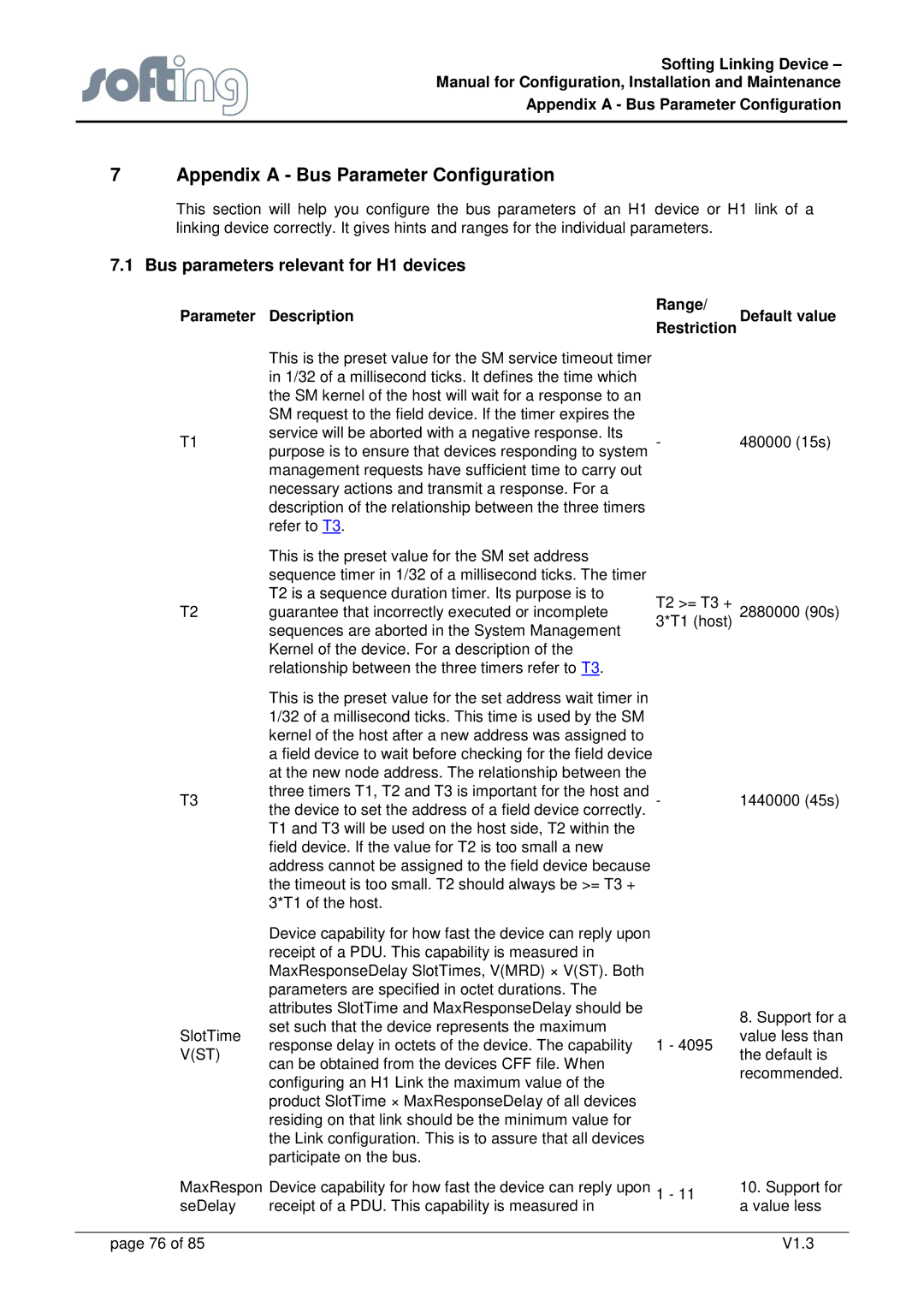
This is the preset value for the SM service timeout timer in 1/32 of a millisecond ticks. It defines the time which the SM kernel of the host will wait for a response to an SM request to the field device. If the timer expires the service will be aborted with a negative response. Its purpose is to ensure that devices responding to system management requests have sufficient time to carry out necessary actions and transmit a response. For a description of the relationship between the three timers refer to T3.

This is the preset value for the SM set address sequence timer in 1/32 of a millisecond ticks. The timer T2 is a sequence duration timer. Its purpose is to guarantee that incorrectly executed or incomplete sequences are aborted in the System Management Kernel of the device. For a description of the relationship between the three timers refer to T3.

This is the preset value for the set address wait timer in 1/32 of a millisecond ticks. This time is used by the SM kernel of the host after a new address was assigned to a field device to wait before checking for the field device at the new node address. The relationship between the three timers T1, T2 and T3 is important for the host and the device to set the address of a field device correctly. T1 and T3 will be used on the host side, T2 within the field device. If the value for T2 is too small a new address cannot be assigned to the field device because the timeout is too small. T2 should always be >= T3 + 3*T1 of the host.

Device capability for how fast the device can reply upon receipt of a PDU. This capability is measured in MaxResponseDelay SlotTimes, V(MRD) × V(ST). Both parameters are specified in octet durations. The attributes SlotTime and MaxResponseDelay should be set such that the device represents the maximum response delay in octets of the device. The capability can be obtained from the devices CFF file. When configuring an H1 Link the maximum value of the product SlotTime × MaxResponseDelay of all devices residing on that link should be the minimum value for the Link configuration. This is to assure that all devices participate on the bus.

-

T2 >= T3 +

3*T1 (host)

-

1 - 4095

480000 (15s)

2880000 (90s)

1440000 (45s)

8.Support for a value less than the default is recommended.

MaxRespon Device capability for how fast the device can reply upon

1 - 11

10. Support for

seDelay

receipt of a PDU. This capability is measured in


a value less


page 76 of 85


V1.3

Page 76
Image 76
Emerson FG-110 manual Bus parameters relevant for H1 devices, Range, Parameter Description

FG-110 specifications

The Emerson FG-110 is a versatile and advanced fire and gas detection system designed for industrial applications. With increasing safety and regulatory standards in industries such as oil and gas, chemical processing, and manufacturing, the FG-110 provides a reliable solution for detecting early signs of fire and gas leaks, ensuring the protection of personnel, assets, and the environment.

One of the key features of the Emerson FG-110 is its robust detection capabilities. It is equipped with a variety of sensors for detecting different types of gases, including combustible gases, toxic gases, and oxygen levels. This multi-sensitivity approach allows for enhanced safety in environments where various hazardous substances may be present. The sensors are designed for high accuracy and fast response times, ensuring that any potential issues are detected swiftly before they escalate into more serious incidents.

The Emerson FG-110 utilizes advanced signal processing technologies. This includes sophisticated algorithms that filter out false alarms, providing operators and safety personnel with reliable notifications. The system's ability to distinguish between genuine threats and harmless environmental changes is crucial in high-stakes environments where false alarms can lead to unnecessary disruptions and safety concerns.

One of the standout characteristics of the FG-110 is its modular design, allowing for flexible configurations tailored to specific site requirements. Users can easily integrate additional sensors or modules as their needs evolve or as they expand their facility. This scalability makes it an ideal choice for both new installations and retrofitting existing systems.

In terms of communications, the Emerson FG-110 supports various protocols, enabling seamless integration with existing safety management systems and centralized control rooms. This connectivity enhances real-time monitoring and data analysis, helping safety teams make informed decisions efficiently.

Built with durability in mind, the Emerson FG-110 meets rigorous industrial standards. Its rugged casing and resistance to harsh environmental conditions ensure long-lasting performance, which is essential for operations in environments exposed to extreme temperatures, vibrations, or corrosive substances.

In summary, the Emerson FG-110 fire and gas detection system combines advanced sensor technologies, reliable performance, and modular design to deliver a comprehensive safety solution for industrial applications. With its focus on accuracy, flexibility, and integration, the FG-110 stands out as a robust tool in maintaining safety and preventing hazards in complex industrial environments.