SECTION 5 OPTIONAL FEATURES
MOTOR LOAD TRANSFER
Inphase monitoring logic controls transfer and retransfer of motor loads, so that inrush currents do not exceed normal starting currents. It avoids nuisance tripping of circuit breakers and mechanical damage to motor couplings.
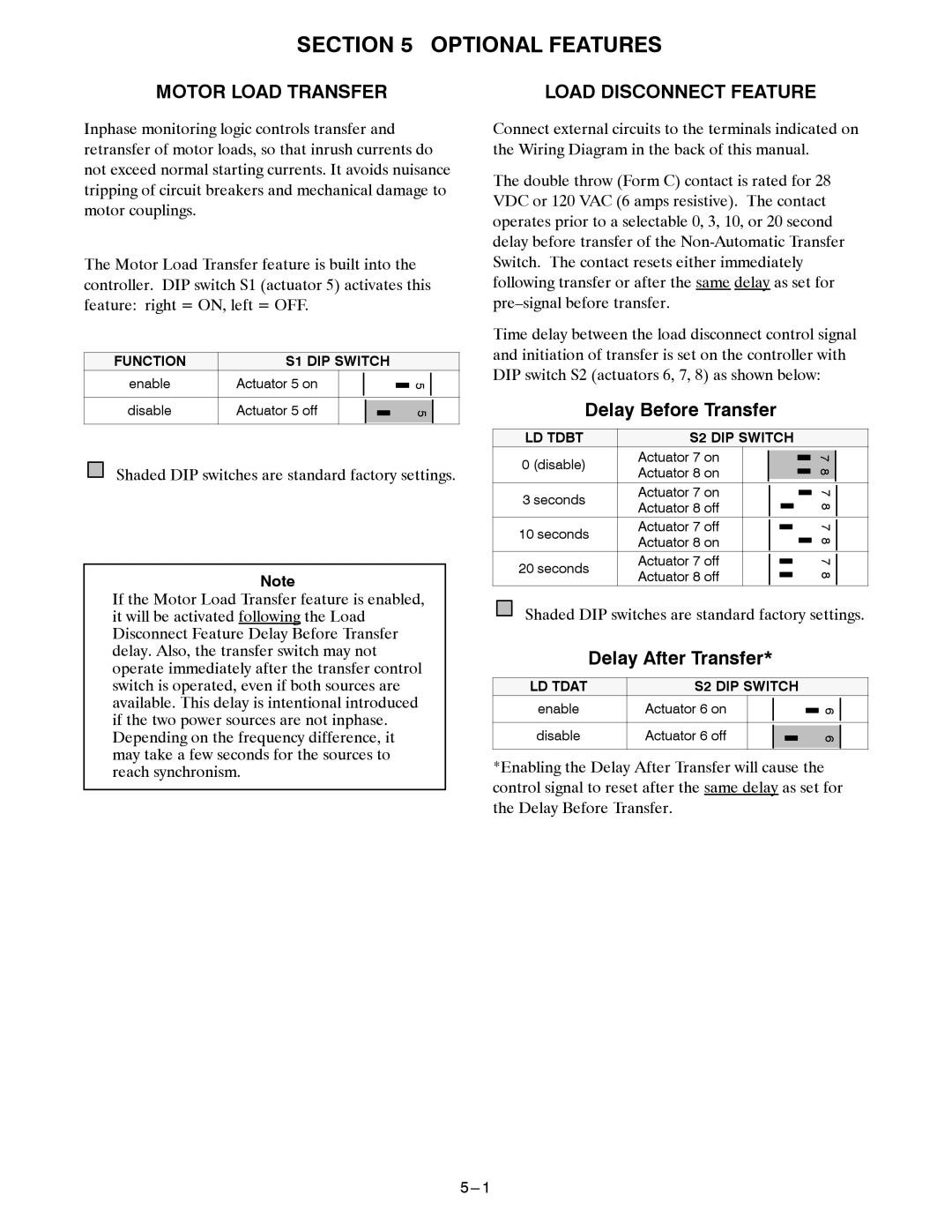
The Motor Load Transfer feature is built into the controller. DIP switch S1 (actuator 5) activates this feature: right = ON, left = OFF.
FUNCTION | S1 DIP SWITCH |
|
|
| ||||
enable | Actuator 5 on |
|
|
|
|
| 5 |
|
|
|
|
|
| ||||
|
|
|
|
|
|
|
|
|
disable | Actuator 5 off |
|
|
|
|
|
|
|
|
|
|
| 5 |
| |||
|
|
|
| |||||
|
|
|
|
|
|
|
|
|
Shaded DIP switches are standard factory settings.
Note
If the Motor Load Transfer feature is enabled, it will be activated following the Load Disconnect Feature Delay Before Transfer delay. Also, the transfer switch may not operate immediately after the transfer control switch is operated, even if both sources are available. This delay is intentional introduced if the two power sources are not inphase. Depending on the frequency difference, it may take a few seconds for the sources to reach synchronism.
LOAD DISCONNECT FEATURE
Connect external circuits to the terminals indicated on the Wiring Diagram in the back of this manual.
The double throw (Form C) contact is rated for 28 VDC or 120 VAC (6 amps resistive). The contact operates prior to a selectable 0, 3, 10, or 20 second delay before transfer of the
Time delay between the load disconnect control signal and initiation of transfer is set on the controller with DIP switch S2 (actuators 6, 7, 8) as shown below:
Delay Before Transfer
LD TDBT | S2 DIP SWITCH |
|
|
|
| ||||||
| Actuator 7 on |
|
|
|
|
|
|
|
|
|
|
0 (disable) |
|
|
|
|
|
| 7 |
| |||
Actuator 8 on |
|
|
|
|
|
|
| 8 |
| ||
|
|
|
|
|
|
|
|
|
| ||
|
|
|
|
|
|
|
|
|
| ||
3 seconds | Actuator 7 on |
|
|
|
|
|
|
| 7 |
| |
|
|
| |||||||||
|
|
|
|
|
| ||||||
Actuator 8 off |
|
|
|
|
|
| 8 |
| |||
|
|
|
|
|
|
|
|
| |||
|
|
|
|
|
|
|
|
|
| ||
10 seconds | Actuator 7 off |
|
|
|
|
| 7 |
| |||
|
| ||||||||||
|
|
|
|
| |||||||
Actuator 8 on |
|
|
|
|
|
|
|
| 8 |
| |
|
|
|
|
|
|
|
|
|
| ||
|
|
|
|
|
|
|
|
| |||
20 seconds | Actuator 7 off |
|
|
| 7 |
| |||||
|
| ||||||||||
|
|
|
|
| |||||||
Actuator 8 off |
|
|
|
|
|
| 8 |
| |||
|
|
|
|
|
|
|
|
| |||
|
|
|
|
|
|
|
|
|
|
|
|
Shaded DIP switches are standard factory settings.
Delay After Transfer*
LD TDAT | S2 DIP SWITCH |
|
|
| ||||
enable | Actuator 6 on |
|
|
|
|
| 6 |
|
|
|
|
|
| ||||
|
|
|
|
|
|
| ||
disable | Actuator 6 off |
|
|
|
|
|
|
|
|
|
|
| 6 |
| |||
|
|
|
| |||||
|
|
|
|
|
|
|
|
|
*Enabling the Delay After Transfer will cause the control signal to reset after the same delay as set for the Delay Before Transfer.