SECTION 1 INSTALLATION
ASCO 386
Remove the Shipping Skid (large N–ATSs)
For large
Supporting Foundation
The supporting foundation for the enclosure must be level and straight. Refer to the applicable enclosure outline drawing included with the switch for all mounting details including door opening space.
If bottom cable entry is used, the foundation must be prepared so that the conduit stubs are located correctly. Refer to the enclosure outline drawing for specified area and location. Provide cable bending space and clearance to live metal parts. When a concrete floor is poured, use interlocking conduit spacer caps or a wood or metal template to maintain proper conduit alignment.
Mounting
Refer to the Outline and Mounting Diagram provided with the
NOTICE
Protect the
Mount the ASCO 386 vertically to a rigid supporting structure. Level all mounting points by using flat washers behind the holes to avoid distortion of the switch.
Auxiliary Cable Boxes for 1000 and 1200 A
For
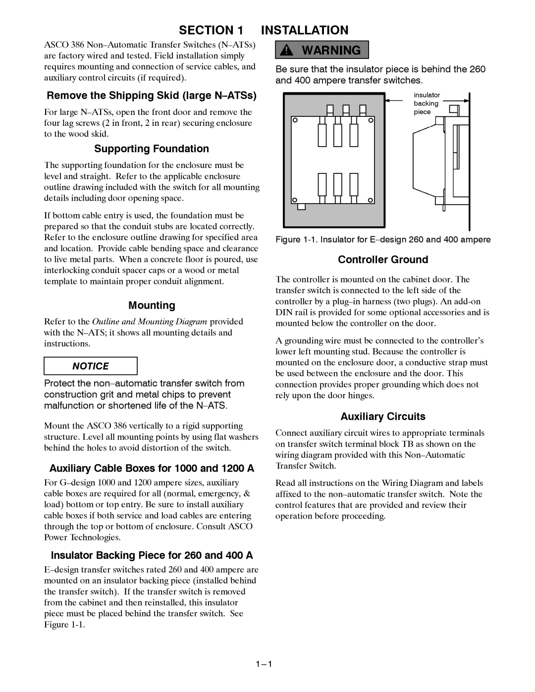
Be sure that the insulator piece is behind the 260 and 400 ampere transfer switches.
insulator backing piece
Figure 1-1. Insulator for E–design 260 and 400 ampere
Controller Ground
The controller is mounted on the cabinet door. The transfer switch is connected to the left side of the controller by a
A grounding wire must be connected to the controller’s lower left mounting stud. Because the controller is mounted on the enclosure door, a conductive strap must be used between the enclosure and the door. This connection provides proper grounding which does not rely upon the door hinges.
Auxiliary Circuits
Connect auxiliary circuit wires to appropriate terminals on transfer switch terminal block TB as shown on the wiring diagram provided with this
Read all instructions on the Wiring Diagram and labels affixed to the