SS-100 specifications
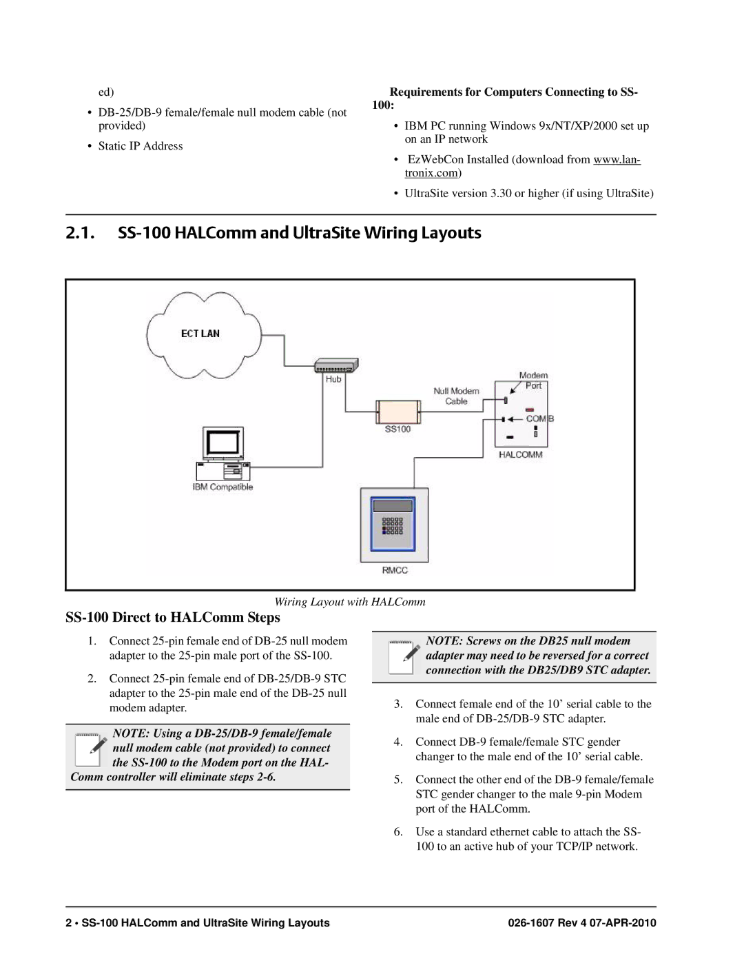
The Emerson SS-100 is a highly regarded device in the field of industrial process control, renowned for its robust performance and advanced features. Designed for various applications, the SS-100 seamlessly integrates into existing systems to enhance efficiency and reliability.One of the primary features of the Emerson SS-100 is its versatile communication capabilities. It supports multiple protocols, including MODBUS, HART, and Foundation Fieldbus, allowing for easy integration with other devices and control systems. This adaptability makes it an ideal choice for facilities looking to modernize their operations without extensive overhauls.
In terms of technology, the SS-100 boasts a state-of-the-art microprocessor that facilitates quick processing speeds and reliable data handling. The unit is equipped with advanced algorithms designed to provide accurate measurements and precise control, essential for maintaining optimal performance in industrial environments. With a high degree of accuracy and responsiveness, the Emerson SS-100 minimizes downtime and enhances productivity.
Another standout characteristic of the SS-100 is its rugged construction. Built to withstand harsh conditions, the device is resistant to dust, moisture, and extreme temperatures. This durability is critical for operations in demanding environments such as oil and gas, chemical processing, and power generation. Additionally, it complies with global safety and efficiency standards, ensuring reliable operation globally.
User-friendly interface and configuration options are also highlights of the Emerson SS-100. Operators can easily access and modify settings through an intuitive display, simplifying the management of process parameters. This features empowers users with the tools needed for effective monitoring and control.
The Emerson SS-100 further supports advanced diagnostic capabilities, providing real-time insights into system performance and health. This feature allows operators to identify potential issues before they escalate, facilitating preventive maintenance and reducing the risk of unplanned outages.
In summary, the Emerson SS-100 encompasses a comprehensive suite of features and technologies that make it a leader in industrial process control. With its flexibility, accuracy, durability, and ease of use, the SS-100 remains an invaluable asset for companies aiming to optimize their operations and enhance overall efficiency.

