Quick Installation Guide
1420 Wireless Gateway
STEP 4 CONTINUED...
Connect to Information System
1.Wire the 1420 Primary Ethernet output or Serial Output connection to the Host System Ethernet or Serial input connections.
2.For Serial connections, connect A to A, B to B and make sure all terminations are clean and secured to avoid wiring connection problems.
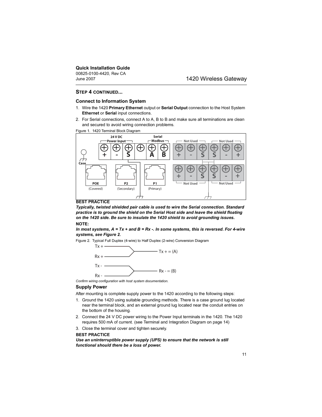
Figure 1. 1420 Terminal Block Diagram
|
|
| 24 V DC |
|
|
|
|
|
|
|
| Serial |
|
|
|
|
|
|
|
|
|
|
|
|
|
| |||||||||||||||||||
|
|
| Power Input |
|
|
|
|
|
|
|
|
|
|
|
| Modbus |
|
|
|
|
| Not Used |
|
|
|
| Not Used | ||||||||||||||||||
|
|
|
|
|
|
|
|
|
|
|
|
|
|
|
|
|
|
|
|
|
|
|
|
|
|
|
|
|
|
|
|
|
|
|
|
|
|
|
|
|
|
|
|
| |
|
|
|
|
|
|
|
|
|
|
|
|
|
|
|
|
|
|
|
|
|
|
|
|
|
|
|
|
|
|
|
|
|
|
|
|
|
|
|
|
|
|
|
|
|
|
|
|
|
|
|
|
|
|
|
|
|
|
|
|
|
|
|
|
|
|
|
|
|
|
|
|
|
|
|
|
|
|
|
|
|
|
|
|
|
|
|
|
|
|
|
|
| + |
| - |
|
|
| S |
|
|
|
|
|
| A |
| B |
|
|
|
|
|
|
|
|
|
|
|
|
|
| |||||||||||||||
|
|
|
|
|
|
|
|
|
|
| + |
|
|
| S | S |
|
|
|
|
| ||||||||||||||||||||||||
|
|
|
|
|
|
|
|
|
|
|
|
|
|
| + | ||||||||||||||||||||||||||||||
|
|
|
|
|
|
|
|
|
|
|
|
|
|
|
|
|
| ||||||||||||||||||||||||||||
|
|
|
|
|
|
|
|
|
|
|
|
|
|
| |||||||||||||||||||||||||||||||
|
|
|
|
|
|
|
|
|
|
|
|
|
|
|
|
| |||||||||||||||||||||||||||||
|
|
|
|
|
|
|
|
|
|
|
|
|
|
|
|
|
|
|
|
|
|
|
|
|
|
|
|
|
|
|
|
|
|
|
|
|
|
|
|
|
|
|
|
|
|
Case
POEP2
(Covered) (Secondary)
|
|
|
|
|
|
|
|
|
|
|
|
|
|
|
|
|
|
|
|
|
| - |
|
|
|
|
|
|
|
|
|
|
|
|
|
|
|
|
|
|
|
|
|
|
|
|
|
| |
|
|
|
|
|
|
|
|
|
|
|
|
|
|
|
|
|
|
|
|
|
|
|
| |
|
|
|
|
|
|
|
|
|
|
|
| + |
|
|
| S |
|
| S |
|
|
| + | |
|
|
|
|
|
|
|
|
|
|
|
|
|
|
|
|
|
|
|
|
| ||||
|
|
| ||||||||||||||||||||||
|
|
|
|
|
|
|
|
|
|
|
|
|
|
|
|
|
|
|
|
|
|
|
|
|
|
|
|
|
| P1 | Not Used | Not Used | |||||||||||||||||
(Primary)
BEST PRACTICE
Typically, twisted shielded pair cable is used to wire the Serial connection. Standard practice is to ground the shield on the Serial Host side and leave the shield floating on the 1420 side. Be sure to insulate the 1420 shield to avoid grounding issues.
NOTE:
In most systems, A = Tx + and B = Rx
Figure 2. Typical Full Duplex (4-wire) to Half Duplex (2-wire) Conversion Diagram
Tx +
Tx + = (A)
Rx +
Tx -
Rx - = (B)
Rx -
Confirm wiring configuration with host system documentation.
Supply Power
After mounting is complete supply power to the 1420 according to the following steps:
1.Ground the 1420 using suitable grounding methods. There is a case ground lug located near the terminal block, and an external ground lug located near the conduit entries on the bottom of the housing.
2.Connect the 24 V DC power wiring to the Power Input terminals in the 1420. The 1420 requires 500 mA of current. (see Terminal and Integration Diagram on page 14)
3.Close the terminal cover and tighten securely.
BEST PRACTICE
Use an uninterruptible power supply (UPS) to ensure that the network is still functional should there be a loss of power.
11