STEP 4. Connecting input and output wiring
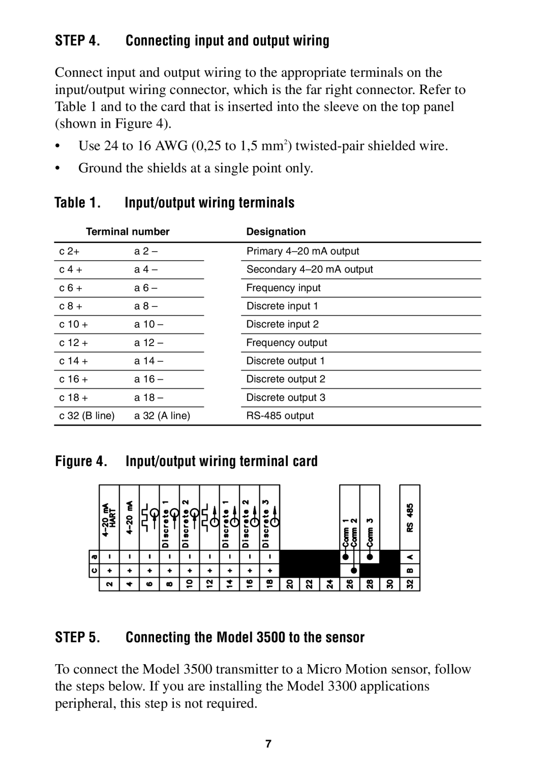
Connect input and output wiring to the appropriate terminals on the input/output wiring connector, which is the far right connector. Refer to Table 1 and to the card that is inserted into the sleeve on the top panel (shown in Figure 4).
•Use 24 to 16 AWG (0,25 to 1,5 mm2)
•Ground the shields at a single point only.
Table 1. Input/output wiring terminals
Terminal number | Designation |
c 2+ | a 2 – | ||
|
| ||
c 4 + | a 4 – | ||
|
| ||
c 6 + | a 6 – | ||
|
| ||
c 8 + | a 8 – | ||
|
| ||
c 10 + | a 10 – | ||
|
| ||
c 12 + | a 12 – | ||
|
|
|
|
c 14 | + | a 14 | – |
|
|
|
|
c 16 | + | a 16 | – |
|
|
|
|
c 18 | + | a 18 | – |
|
|
|
|
c 32 | (B line) | a 32 | (A line) |
Primary
Secondary
Frequency input
Discrete input 1
Discrete input 2
Frequency output
Discrete output 1
Discrete output 2
Discrete output 3
Figure 4. Input/output wiring terminal card
STEP 5. Connecting the Model 3500 to the sensor
To connect the Model 3500 transmitter to a Micro Motion sensor, follow the steps below. If you are installing the Model 3300 applications peripheral, this step is not required.
7