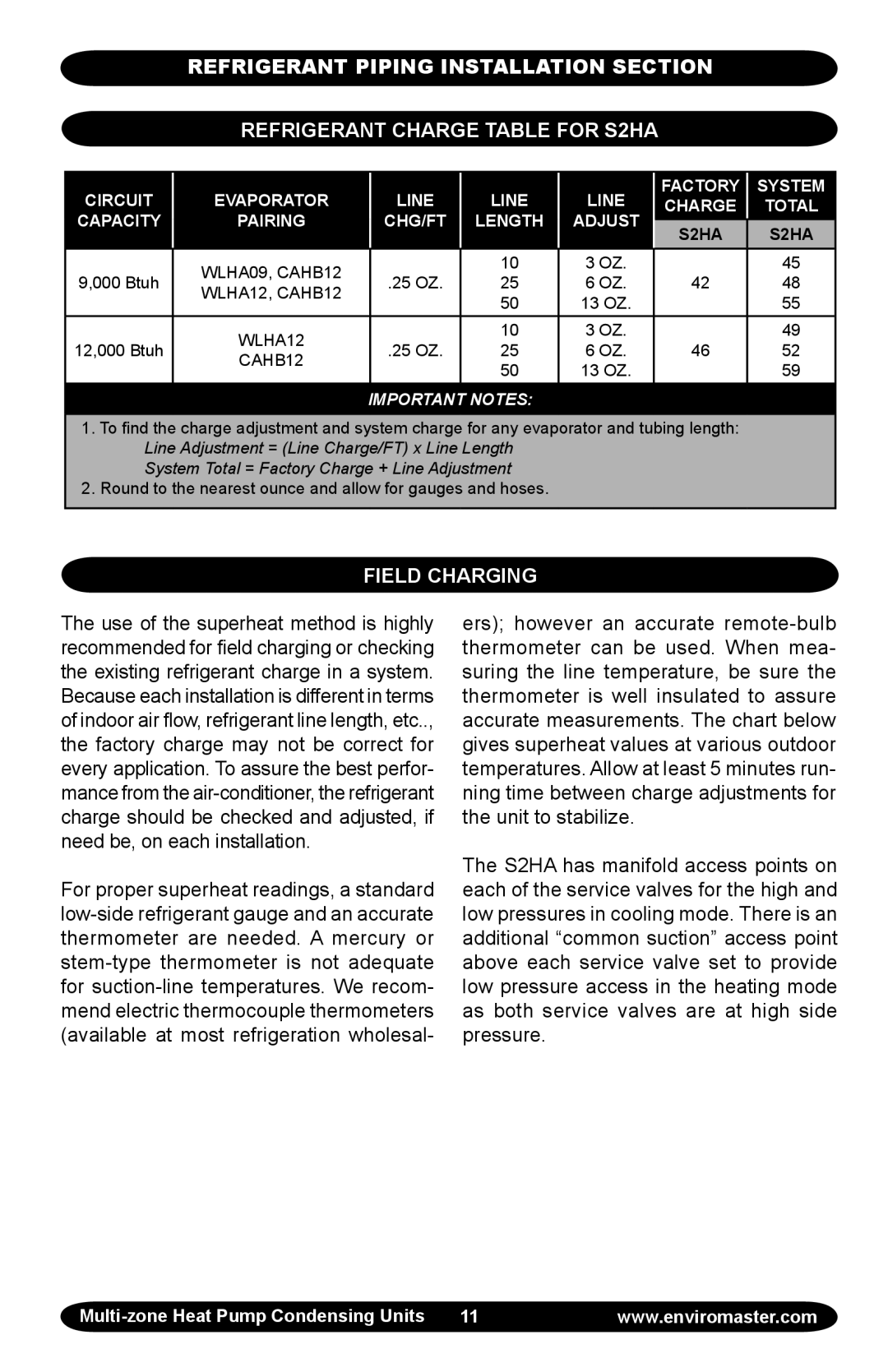
EMI Corp specifications
EMI EMI Corp is a prominent organization in the technology sector, particularly known for its advanced electronic manufacturing solutions. Established with a vision to provide innovative design and engineering services, EMI has set itself apart through its commitment to quality and customer satisfaction. The company offers a diverse range of products and services, catering to various industries, including aerospace, automotive, telecommunications, and consumer electronics.One of the key features of EMI is its state-of-the-art manufacturing facilities equipped with the latest technologies. The company employs advanced automation and robotics in its production processes, allowing for higher efficiency and precision. This not only reduces the potential for human error but also accelerates the manufacturing timeline, ensuring timely delivery of products.
EMI also places a strong emphasis on research and development. With a dedicated team of engineers and technologists, the company invests heavily in exploring new materials, refining manufacturing techniques, and developing proprietary technologies. This commitment to innovation has led to the creation of several industry-leading products, including high-performance printed circuit boards (PCBs) and custom electronic assemblies.
Another characteristic that differentiates EMI is its focus on sustainability. The company has implemented eco-friendly practices throughout its operations, striving to minimize waste and reduce its carbon footprint. By using sustainable materials and energy-efficient processes, EMI is dedicated to contributing positively to the environment while maintaining robust growth and profitability.
Furthermore, EMI EMI Corp prides itself on its strong customer relationships. The company understands that collaboration is essential for success and works closely with clients to tailor solutions that meet their specific needs. This customer-centric approach ensures that every product delivered aligns with the client’s requirements, enhancing satisfaction and fostering long-term partnerships.
In conclusion, EMI EMI Corp stands out in the technology landscape due to its advanced manufacturing capabilities, commitment to innovation, focus on sustainability, and dedication to customer service. As technology continues to evolve, EMI remains poised to adapt and lead in the competitive electronic manufacturing sector, making significant contributions to various industries worldwide.

