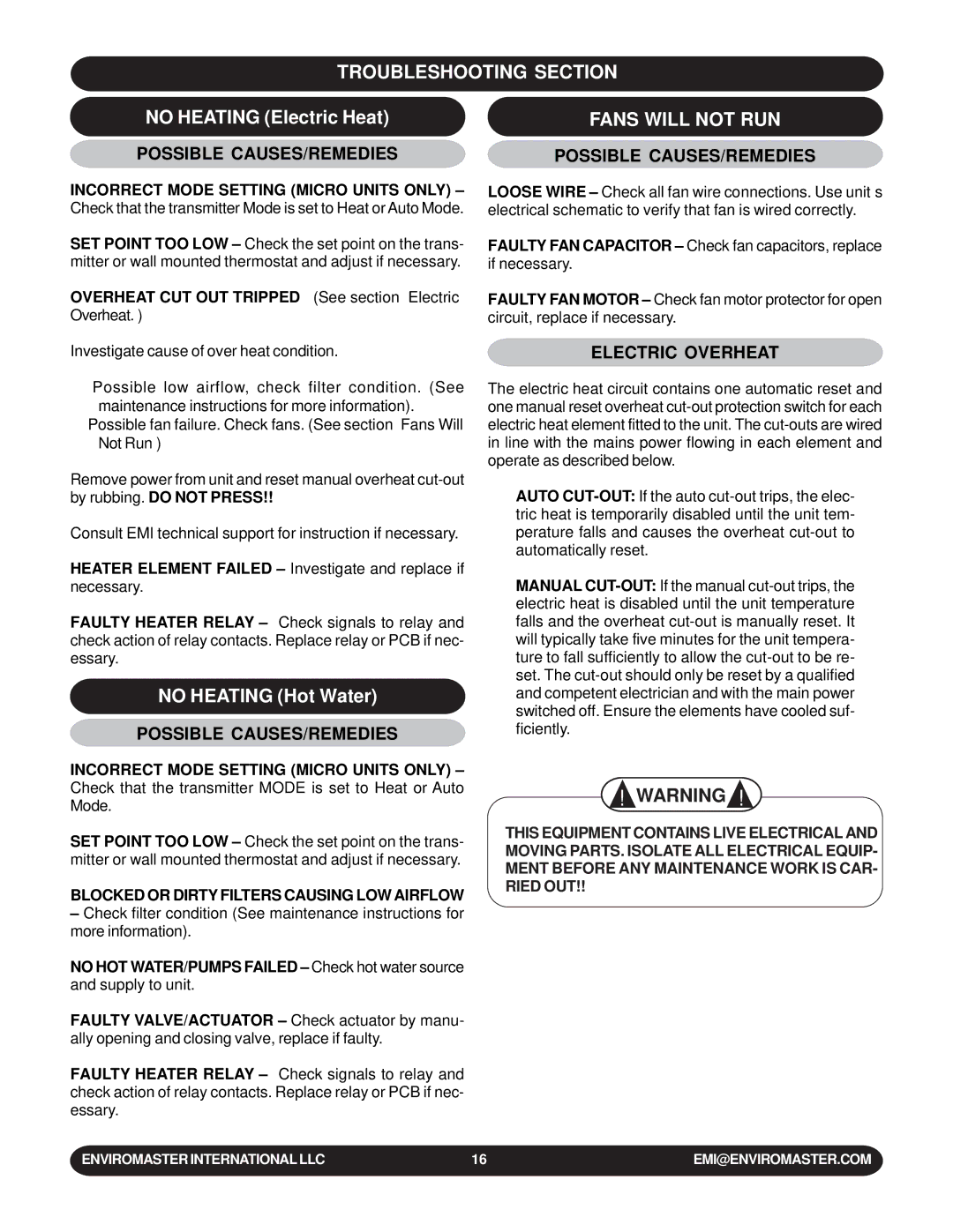
TROUBLESHOOTING SECTION

NO HEATING (Electric Heat)

FANS WILL NOT RUN

POSSIBLE CAUSES/REMEDIES

POSSIBLE CAUSES/REMEDIES

INCORRECT MODE SETTING (MICRO UNITS ONLY) – Check that the transmitter Mode is set to Heat or Auto Mode.

SET POINT TOO LOW – Check the set point on the trans- mitter or wall mounted thermostat and adjust if necessary.

OVERHEAT CUT OUT TRIPPED – (See section “Electric Overheat.”)

Investigate cause of over heat condition.

Possible low airflow, check filter condition. (See maintenance instructions for more information).

Possible fan failure. Check fans. (See section “Fans Will Not Run”)

Remove power from unit and reset manual overheat cut-out by rubbing. DO NOT PRESS!!

Consult EMI technical support for instruction if necessary.

HEATER ELEMENT FAILED – Investigate and replace if necessary.

FAULTY HEATER RELAY – Check signals to relay and check action of relay contacts. Replace relay or PCB if nec- essary.

NO HEATING (Hot Water)

POSSIBLE CAUSES/REMEDIES

INCORRECT MODE SETTING (MICRO UNITS ONLY) – Check that the transmitter MODE is set to Heat or Auto Mode.

SET POINT TOO LOW – Check the set point on the trans- mitter or wall mounted thermostat and adjust if necessary.

BLOCKED OR DIRTY FILTERS CAUSING LOW AIRFLOW

Check filter condition (See maintenance instructions for more information).

NO HOT WATER/PUMPS FAILED – Check hot water source and supply to unit.

FAULTY VALVE/ACTUATOR – Check actuator by manu- ally opening and closing valve, replace if faulty.

FAULTY HEATER RELAY – Check signals to relay and check action of relay contacts. Replace relay or PCB if nec- essary.

LOOSE WIRE – Check all fan wire connections. Use unit’s electrical schematic to verify that fan is wired correctly.

FAULTY FAN CAPACITOR – Check fan capacitors, replace if necessary.

FAULTY FAN MOTOR – Check fan motor protector for open circuit, replace if necessary.

ELECTRIC OVERHEAT

The electric heat circuit contains one automatic reset and one manual reset overheat cut-out protection switch for each electric heat element fitted to the unit. The cut-outs are wired in line with the mains power flowing in each element and operate as described below.

AUTO CUT-OUT:If the auto cut-out trips, the elec- tric heat is temporarily disabled until the unit tem- perature falls and causes the overheat cut-out to automatically reset.

MANUAL CUT-OUT:If the manual cut-out trips, the electric heat is disabled until the unit temperature falls and the overheat cut-out is manually reset. It will typically take five minutes for the unit tempera- ture to fall sufficiently to allow the cut-out to be re- set. The cut-out should only be reset by a qualified and competent electrician and with the main power switched off. Ensure the elements have cooled suf- ficiently.

! WARNING !

THIS EQUIPMENT CONTAINS LIVE ELECTRICAL AND MOVING PARTS. ISOLATE ALL ELECTRICAL EQUIP- MENT BEFORE ANY MAINTENANCE WORK IS CAR- RIED OUT!!

ENVIROMASTER INTERNATIONAL LLC

16

EMI@ENVIROMASTER.COM

Page 16
Image 16
EMI WLCA installation manual Fans will not RUN, Possible CAUSES/REMEDIES, Electric Overheat

WLCA specifications

EMI WLCA, or Electromagnetic Interference Wireless Lightning Control Architecture, represents a groundbreaking evolution in the realm of electromagnetic interference mitigation technologies. Designed to safeguard sensitive electronic systems from the potentially detrimental effects of electromagnetic disturbances, EMI WLCA integrates a host of advanced features and characteristics that empower both industries and consumers.

One of the primary features of EMI WLCA is its ability to operate across various frequencies. This versatility ensures that it can mitigate interference from a wide range of sources, whether they originate from industrial machinery, communication devices, or environmental factors. By effectively filtering out these unwanted signals, the technology facilitates more stable and reliable performance in electronic systems.

At the heart of EMI WLCA lie several state-of-the-art technologies that enhance its efficiency. Adaptive filtering is a key component, allowing the system to dynamically adjust its response based on the detected interference levels. This real-time adjustment capability ensures optimal performance, minimizing lag and improving responsiveness in critical applications, such as aviation, telecommunications, and medical devices.

Another notable characteristic of EMI WLCA is its modular design. This allows for easy integration into existing systems, enabling manufacturers to incorporate the technology without necessitating an overhaul of their current infrastructure. The modularity also facilitates future upgrades, ensuring that systems can adapt to changing standards and emerging interferences.

In addition to its impressive technical specifications, EMI WLCA is designed with user-friendliness in mind. Comprehensive monitoring tools provide users with insightful data on interference levels and the effectiveness of the mitigation strategies being employed. This transparency not only aids in troubleshooting but also enhances overall system performance by allowing users to make informed adjustments as needed.

Moreover, EMI WLCA is built to meet stringent regulatory compliance standards. This ensures its broad applicability across various sectors, including aerospace, automotive, and consumer electronics. As technology continues to advance, the RF environment becomes increasingly crowded, making solutions like EMI WLCA not only desirable but essential.

In conclusion, EMI WLCA stands out as a significant advancement in electromagnetic interference control technology. With its adaptive filtering capabilities, modular design, user-friendly monitoring tools, and compliance with industry regulations, EMI WLCA promises to enhance the reliability and performance of electronic systems across diverse applications. As the demand for interference-resistant technology grows, innovations like EMI WLCA will undoubtedly play a critical role in shaping the future of electronic design and implementation.