displayed on the fascia mounted receiver. The microproces- sor also limits the number of compressor starts per hour to reduce wear on the compressor.

The infrared transmitter is used to switch the unit on/off, change temperature settings, fan speed, operating mode and to toggle the motorized air sweep (where fitted). The micro- processor also has a built-in clock which can be activated to enable the unit to be programmed with up to two separate operating periods for the days of the week (Mon-Fri). The clock provides On/Off unit operation and is not a night set back or occupied/unoccupied control function. Mon-Fri will operate as a ‘block’ of days and cannot be programmed independently of one another. Saturdays and Sundays can each be programmed with up to two separate operating pe- riods and are programmed independently of weekdays and each other.

A fascia mounted receiver displays On/Off, cool or heat and timer/alarm status.

FILTERS: Wire framed filters are fitted. These are reusable and may be vacuum cleaned.

CONDENSATE PUMP: A condensate pump is fitted to carry water out of the unit. The pump is fixed to a mounting bracket which can be withdrawn from the side of the chassis and incorporates an inspection hole to allow a visual check of the pump during operation. A float switch is fitted to stop the cooling action should the pump become blocked or fail.

IMPORTANT: TOTAL LIFT FOR THIS PUMP

IS 18” OR LESS.

AIR VANES: Air outlet vanes are manufactured from alumi- num and covered with nylon flock to prevent condensation from forming. Vanes are manually adjustable on the 2 x 2 model units or driven by an electric motor on all other model units. Where fitted, the motorized air vanes can be set to auto sweep or can be stopped in a fixed position.

HEATING: The cassette may be fitted with either electric heaters or a hot water coil. It is recommended that heat pumps be fitted with the electric heat option to offset the defrost cycle. Electric heaters are fitted with over-heat cut out switches.

FRESH AIR CONNECTION: Fresh air may be introduced to the unit by the addition of ducts connected to the fresh air knockouts on the Cassette case. It is usually advised that the fresh air volume is approximately 10% of the unit’s pub- lished maximum air flow.

SITE INSTALLATION

UNPACKING: The cassette fascia and main chassis are supplied together for increased protection. Remove the band- ing straps and lift the cardboard lid. Remove the bubble wrap and polystyrene packing pieces to expose the unit. The fas- cia should be unpacked first by unclipping the inlet grille and

loosening the four M5 screws retaining the fascia in place. The fascia can now be slid sideways and pulled away from the chassis. When removing the Cassette chassis from the box the four corner brackets should be utilized for lifting. In order to protect the fascia from dirt and damage, it should be returned to the box until it is ready to be installed.

BLANKING OFF: When branch ducting is to be used, two polystyrene pieces for blanking off fascia open- ings are Included with the fascia packing. Up to two opposing sides may be blanked off.

POSITIONING

CASSETTE - The Cassette installation position should be selected with the following points in mind:

1.Pipe work, electrical connections and condensate pump access panel should be readily accessible.

2.When installing a unit with an externally mounted electrical control panel, ensure that sufficient access to the panel is provided for maintenance purposes. Access to the condensate pump access panel should be provided on all model sizes.

3.The unit should not be positioned less than 5 ft. from a wall or similar obstruction, or in a position where the discharge air could blow directly on the thermostat.

4.The unit should not be positioned directly above any obstructions.

5.The condensate drain should have sufficient fall (1” per 10’) in any horizontal run between Cassette and drain. Maximum condensate pump lift is 18".

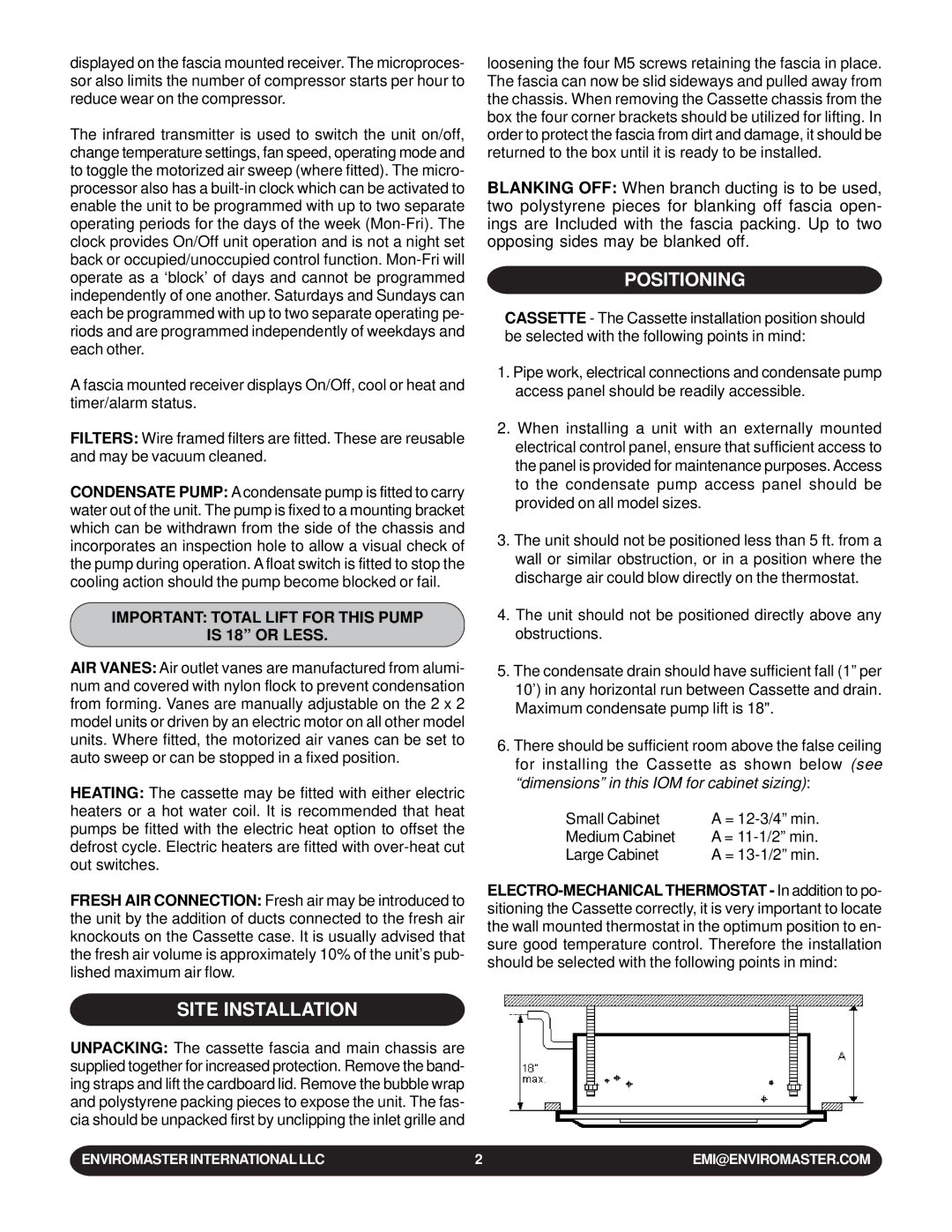
6.There should be sufficient room above the false ceiling for installing the Cassette as shown below (see “dimensions” in this IOM for cabinet sizing):

Small Cabinet

A = 12-3/4” min.

Medium Cabinet

A = 11-1/2” min.

Large Cabinet

A = 13-1/2” min.

ELECTRO-MECHANICAL THERMOSTAT - In addition to po- sitioning the Cassette correctly, it is very important to locate the wall mounted thermostat in the optimum position to en- sure good temperature control. Therefore the installation should be selected with the following points in mind:

ENVIROMASTER INTERNATIONAL LLC

2

EMI@ENVIROMASTER.COM

Page 2
Image 2
EMI WLCA installation manual Site Installation, Positioning

WLCA specifications

EMI WLCA, or Electromagnetic Interference Wireless Lightning Control Architecture, represents a groundbreaking evolution in the realm of electromagnetic interference mitigation technologies. Designed to safeguard sensitive electronic systems from the potentially detrimental effects of electromagnetic disturbances, EMI WLCA integrates a host of advanced features and characteristics that empower both industries and consumers.

One of the primary features of EMI WLCA is its ability to operate across various frequencies. This versatility ensures that it can mitigate interference from a wide range of sources, whether they originate from industrial machinery, communication devices, or environmental factors. By effectively filtering out these unwanted signals, the technology facilitates more stable and reliable performance in electronic systems.

At the heart of EMI WLCA lie several state-of-the-art technologies that enhance its efficiency. Adaptive filtering is a key component, allowing the system to dynamically adjust its response based on the detected interference levels. This real-time adjustment capability ensures optimal performance, minimizing lag and improving responsiveness in critical applications, such as aviation, telecommunications, and medical devices.

Another notable characteristic of EMI WLCA is its modular design. This allows for easy integration into existing systems, enabling manufacturers to incorporate the technology without necessitating an overhaul of their current infrastructure. The modularity also facilitates future upgrades, ensuring that systems can adapt to changing standards and emerging interferences.

In addition to its impressive technical specifications, EMI WLCA is designed with user-friendliness in mind. Comprehensive monitoring tools provide users with insightful data on interference levels and the effectiveness of the mitigation strategies being employed. This transparency not only aids in troubleshooting but also enhances overall system performance by allowing users to make informed adjustments as needed.

Moreover, EMI WLCA is built to meet stringent regulatory compliance standards. This ensures its broad applicability across various sectors, including aerospace, automotive, and consumer electronics. As technology continues to advance, the RF environment becomes increasingly crowded, making solutions like EMI WLCA not only desirable but essential.

In conclusion, EMI WLCA stands out as a significant advancement in electromagnetic interference control technology. With its adaptive filtering capabilities, modular design, user-friendly monitoring tools, and compliance with industry regulations, EMI WLCA promises to enhance the reliability and performance of electronic systems across diverse applications. As the demand for interference-resistant technology grows, innovations like EMI WLCA will undoubtedly play a critical role in shaping the future of electronic design and implementation.