CONNECTING WET/DRY GRINDER
TO POWER SOURCE
POWER CONNECTIONS
A separate electrical circuit should be used for your tools. This circuit should not be less than #12 wire and should be protected with a 20 Amp time lag fuse. If an extension cord is used, use only
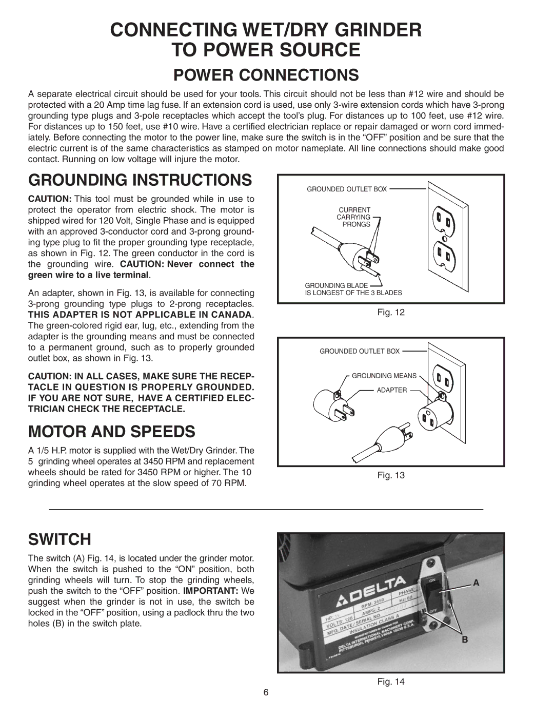
GROUNDING INSTRUCTIONS
CAUTION: This tool must be grounded while in use to protect the operator from electric shock. The motor is shipped wired for 120 Volt, Single Phase and is equipped with an approved
An adapter, shown in Fig. 13, is available for connecting
THIS ADAPTER IS NOT APPLICABLE IN CANADA. The
CAUTION: IN ALL CASES, MAKE SURE THE RECEP- TACLE IN QUESTION IS PROPERLY GROUNDED. IF YOU ARE NOT SURE, HAVE A CERTIFIED ELEC- TRICIAN CHECK THE RECEPTACLE.
MOTOR AND SPEEDS
A 1/5 H.P. motor is supplied with the Wet/Dry Grinder. The
5grinding wheel operates at 3450 RPM and replacement wheels should be rated for 3450 RPM or higher. The 10 grinding wheel operates at the slow speed of 70 RPM.
GROUNDED OUTLET BOX
CURRENT
CARRYING
PRONGS
GROUNDING BLADE
IS LONGEST OF THE 3 BLADES
Fig. 12
GROUNDED OUTLET BOX
GROUNDING MEANS
ADAPTER
Fig. 13
SWITCH
The switch (A) Fig. 14, is located under the grinder motor. When the switch is pushed to the “ON” position, both grinding wheels will turn. To stop the grinding wheels, push the switch to the “OFF” position. IMPORTANT: We suggest when the grinder is not in use, the switch be locked in the “OFF” position, using a padlock thru the two holes (B) in the switch plate.
A
B
Fig. 14
6