Section 6
Wiring
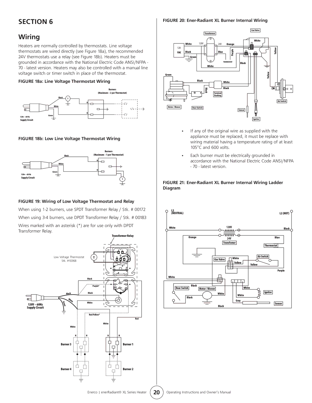
FIGURE 20: Ener-Radiant XL Burner Internal Wiring
Gas Valve
Transformer
Heaters are normally controlled by thermostats. Line voltage thermostats are wired directly (see Figure 18a), the recommended 24V thermostats use a relay (see Figure 18b). Heaters must be grounded in accordance with the National Electric Code ANSI/NFPA - 70 - latest version. Heaters may also be controlled with a manual line
| White | 120V | 24V | Orange |
|
120 |
|
|
| Purple |
|
VAC | Black |
| Blue |
| |
|
|
| |||
| Green |
|
|
|
|
|
|
|
| THERMOSTAT | Black |
|
|
| White |
| |
|
|
|
|
|
White
Yellow
voltage switch or timer switch in place of the thermostat.
FIGURE 18a: Line Voltage Thermostat Wiring
Burners
(Maximum – 2 per Thermostat)
Black T
H
White
N
120v – 60 Hz | Green |
|
Green
Motor / Blower
Black
Black
Door Switch
White
Black
Terminal
Bushing
Sensor
Yellow
Air Switch
Supply Circuit
FIGURE 18b: Low Line Voltage Thermostat Wiring
|
|
|
|
|
|
|
|
|
|
|
|
|
| Burners |
| |||||
|
|
|
|
|
|
|
|
|
| Black | (Maximum – 1 per Thermostat) |
| ||||||||
|
|
|
|
|
|
|
|
|
|
|
|
|
|
|
|
|
|
| ||
|
|
|
|
|
|
| White | H |
|
|
|
|
|
|
|
|
| |||
|
|
|
|
|
|
| N |
|
|
|
|
|
|
|
|
| ||||
|
|
|
| Green |
|
|
|
|
|
|
|
|
|
|
|
|
| |||
|
|
|
|
|
|
|
|
|
|
|
|
|
|
|
| |||||
|
|
|
|
|
|
|
|
| ||||||||||||
120v – 60 Hz |
|
|
|
|
|
|
|
|
|
|
|
|
|
|
|
| ||||
|
|
|
|
|
|
|
|
|
|
|
|
|
| |||||||
Supply Circuit |
|
|
|
|
|
|
|
|
|
|
|
|
|
| ||||||
|
|
|
|
|
|
|
|
|
|
|
| T |
| |||||||
|
|
|
|
|
|
|
|
|
|
|
|
|
|
|
|
|
|
| ||
|
|
|
|
|
|
|
|
|
|
|
|
|
|
|
|
|
|
|
|
|
|
|
|
|
|
|
|
|
|
|
|
|
|
|
|
|
|
|
|
|
|
|
|
|
|
|
|
|
|
|
|
|
|
|
|
|
|
|
|
|
|
|
FIGURE 19: Wiring of Low Voltage Thermostat and Relay
When using
Wires marked with an asterisk (*) are for use only with DPDT Transformer Relay.
Transformer Relay
Ignitor
•If any of the original wire as supplied with the appliance must be replaced, it must be replace with wiring material having a temperature rating of at least 105°C and 600 volts.
•Each burner must be electrically grounded in accordance with the National Electric Code ANSI/NFPA - 70 - latest version.
FIGURE 21: Ener-Radiant XL Burner Internal Wiring Ladder Diagram
L2 |
| L2 (HOT) |
(NEUTRAL) |
| |
White | 120V | Black |
|
| |
Orange | 24V | Blue |
|
| |
| Transfomer |
|
120V – 60Hz
Supply Circuit
|
|
|
| B | C |
|
Low Voltage Thermostat | T | W | G |
| Y | |
Stk. #10368 |
|
|
|
|
| |
|
| Black |
|
|
| 3 |
|
|
|
|
|
| |
|
|
| 4 |
| 2 | 6 |
|
| Purple* |
|
| ||
|
|
|
| 5 |
| |
|
|
|
|
|
| |
Black | Black |
|
|
|
| |
Green | White | White |
|
|
|
|
|
|
|
|
| ||
|
|
|
|
|
| |
|
| Red/Yellow* |
|
|
|
|
|
|
|
|
|
| Red |
|
|
| White |
|
|
|
| White |
|
|
|
|
|
N | H | N | H |
Burner 3 |
|
| Burner 1 |
Thermostat |
|
| Gas Valve | White | Air Switch |
|
|
| ||
|
| Yellow |
| |
|
|
| Yellow | |
|
|
|
| |
|
|
|
| Purple |
White |
|
|
|
|
Door Switch | Black | Motor / Blower | White |
|
| Ignitor | |||
|
| White | White | |
|
|
| ||
Black |
|
| ||
| Gray |
| ||
|
|
| Sensor | |
|
| Black |
| |
|
|
|
| |
Burner 4 | Burner 2 |
Enerco enerRadiant® XL Series Heater | 20 | Operating Instructions and Owner’s Manual |