VH-8TX1MF, VH-8TX1UM specifications
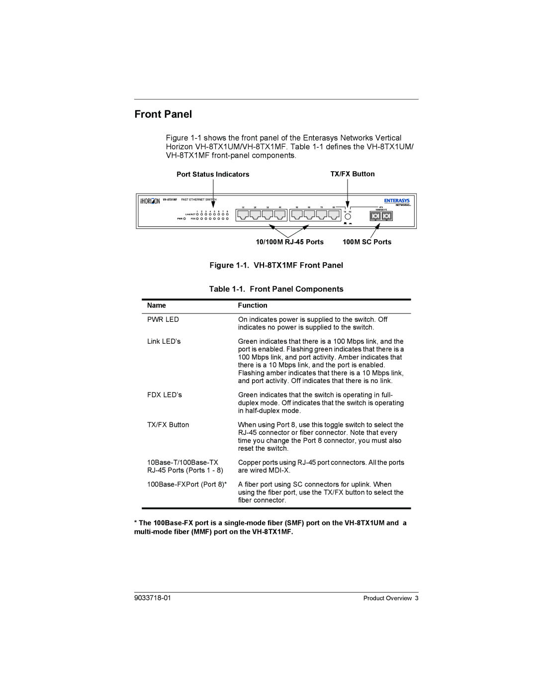
Enterasys Networks, a well-respected name in the field of networking technology, has introduced the VH-8TX1UM and VH-8TX1MF models, which cater to the ever-evolving needs of modern enterprises. These devices are designed to enhance connectivity, improve network performance, and provide enhanced security for users across various environments.The VH-8TX1UM model is a versatile Layer 2/3 managed switch that features eight 10/100/1000BASE-T Ethernet ports. This configuration allows for seamless connectivity with existing network infrastructure while providing the necessary throughput for bandwidth-hungry applications. It supports a range of features including VLAN tagging, port mirroring, and link aggregation, making it ideal for both small and medium-sized businesses looking to scale their networks without significant hardware investments.
Meanwhile, the VH-8TX1MF model is designed with a focus on modularity. It not only features eight Ethernet ports but also includes slots for additional modules, allowing organizations to customize their network setup based on specific requirements. The modular design ensures flexibility, enabling future upgrades without the need for complete hardware replacements. This characteristic is particularly beneficial for companies that anticipate growth or changes in their network architecture.
Both models boast advanced technologies such as Quality of Service (QoS) and Power over Ethernet (PoE). QoS prioritizes critical network traffic, ensuring that voice and video applications receive the bandwidth they need for optimal performance. PoE allows for the powering of devices like IP cameras, phones, and wireless access points directly through the Ethernet cables, simplifying installations and reducing the need for additional power sources.
In terms of security, Enterasys equips the VH-8TX1UM and VH-8TX1MF with robust features to safeguard sensitive data. These include access control lists and port security settings, which protect against unauthorized access and mitigate potential threats. Additionally, the switches support network management protocols such as Simple Network Management Protocol (SNMP), enabling efficient monitoring and management of network performance.
Overall, the Enterasys VH-8TX1UM and VH-8TX1MF models stand out with their combination of performance, flexibility, and security. They present a compelling option for enterprises aiming to enhance their networking capabilities while ensuring that they are well-equipped to handle future technological advancements. Businesses investing in these switches are sure to benefit from a solid foundation that can evolve with their operational needs.

