1. All grounded, cord-connected tools:
In the event of a malfunction or breakdown, grounding pro- vides a path of least resistance for electric current to reduce the risk of electric shock. This tool is equipped with an electric cord having an
Do not modify the plug provided - if it will not fit the outlet, have the proper outlet installed by a qualified electrician.
Improper connection of the
Check with a qualified electrician or service personnel if the grounding instructions are not completely understood, or if in doubt as to whether the tool is properly grounded.
Use only
Repair or replace damaged or worn cord immediately.
GROUNDED OUTLET BOX
CURRENT
CARRYING
PRONGS
GROUNDING BLADE
IS LONGEST OF THE 3 BLADES
Fig. 1
2.Grounded,
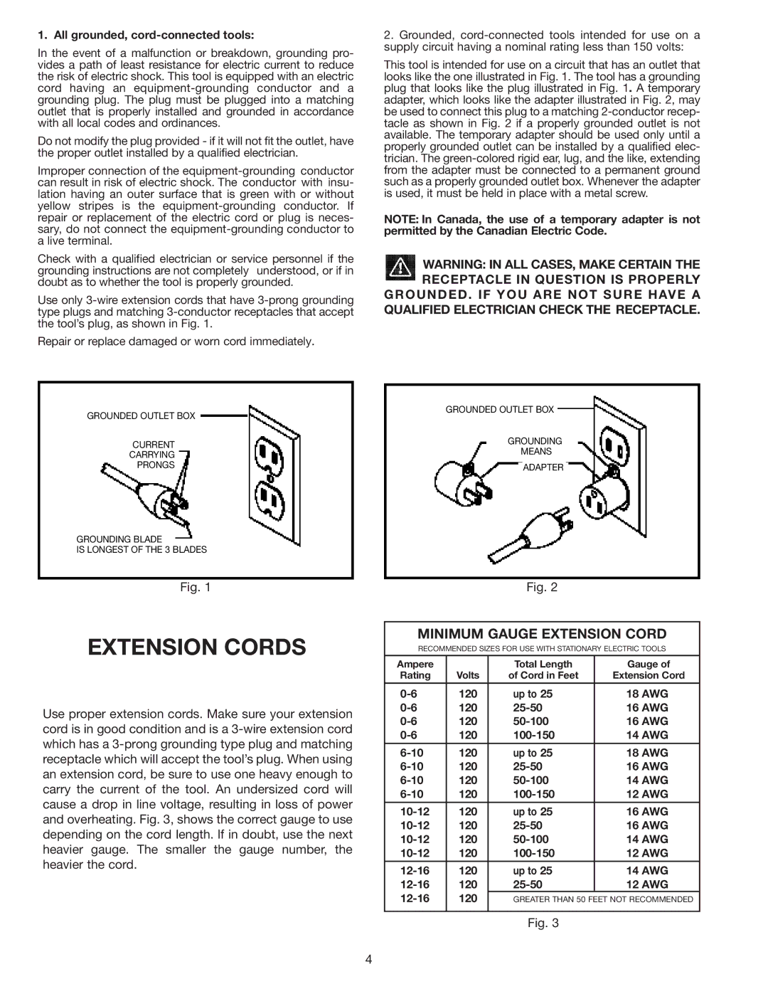
This tool is intended for use on a circuit that has an outlet that looks like the one illustrated in Fig. 1. The tool has a grounding plug that looks like the plug illustrated in Fig. 1. A temporary adapter, which looks like the adapter illustrated in Fig. 2, may be used to connect this plug to a matching
NOTE: In Canada, the use of a temporary adapter is not permitted by the Canadian Electric Code.
WARNING: IN ALL CASES, MAKE CERTAIN THE RECEPTACLE IN QUESTION IS PROPERLY GROUNDED. IF YOU ARE NOT SURE HAVE A QUALIFIED ELECTRICIAN CHECK THE RECEPTACLE.
GROUNDED OUTLET BOX
GROUNDING
MEANS
ADAPTER
Fig. 2
EXTENSION CORDS
Use proper extension cords. Make sure your extension cord is in good condition and is a
MINIMUM GAUGE EXTENSION CORD
RECOMMENDED SIZES FOR USE WITH STATIONARY ELECTRIC TOOLS
Ampere |
| Total Length | Gauge of |
Rating | Volts | of Cord in Feet | Extension Cord |
|
|
|
|
120 | up to 25 | 18 AWG | |
120 | 16 AWG | ||
120 | 16 AWG | ||
120 | 14 AWG | ||
120 | up to 25 | 18 AWG | |
120 | 16 AWG | ||
120 | 14 AWG | ||
120 | 12 AWG | ||
|
|
|
|
120 | up to 25 | 16 AWG | |
120 | 16 AWG | ||
120 | 14 AWG | ||
120 | 12 AWG | ||
120 | up to 25 | 14 AWG | |
120 | 12 AWG | ||
120 | GREATER THAN 50 FEET NOT RECOMMENDED | ||
|
|
|
|
Fig. 3
4
