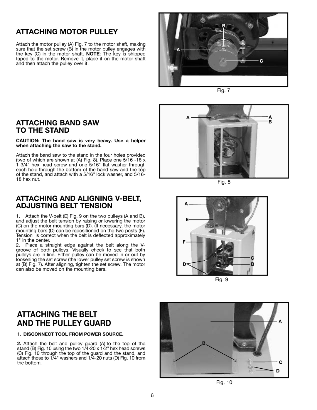
ATTACHING MOTOR PULLEY
Attach the motor pulley (A) Fig. 7 to the motor shaft, making sure that the set screw (B) in the motor pulley engages with the key (C) in the motor shaft. NOTE: The key is shipped taped to the motor. Remove it, place it on the motor shaft and then attach the pulley over it.
B
A
C
ATTACHING BAND SAW
TO THE STAND
CAUTION: The band saw is very heavy. Use a helper when attaching the saw to the stand.
Attach the band saw to the stand in the four holes provided (two of which are shown at (A) Fig. 8). Place one 5/16
ATTACHING AND ALIGNING V-BELT, ADJUSTING BELT TENSION
1.Attach the
(C) on the motor mounting bars (D). (If necessary, the motor mounting bars (D) can be repositioned on the two posts (F). Tension is correct when the belt is deflected approximately 1" in the center.
2.Place a straight edge against the belt along the V- groove of both pulleys. Visually check to see that both pulleys are in line. Either pulley can be moved in or out by loosening the set screw (the lower pulley set screw is shown at (B) Fig. 7). After aligning, tighten the set screw. The motor can also be moved on the mounting bars.
ATTACHING THE BELT
AND THE PULLEY GUARD
1.DISCONNECT TOOL FROM POWER SOURCE.
2.Attach the belt and pulley guard (A) to the top of the stand (B) Fig. 10 using the two
(C) Fig. 10 through the top of the guard and the stand, and attach those to 1/4" washers and 1/4-20 nuts (D) Fig. 10 from the bottom.
Fig. 7
A ![]()
![]() A
A
B
|
|
|
| Fig. 8 | ||
|
|
|
|
|
|
|
A |
|
|
|
| ||
E |
|
|
|
|
| |
|
|
|
|
| ||
F |
|
|
|
|
| C |
|
|
|
|
| ||
|
|
|
|
|
| |
D |
|
|
| B | ||
|
|
| ||||
|
|
|
|
|
|
|
Fig. 9
A |
B |
C |
D |
Fig. 10
6