TABLE INSERT
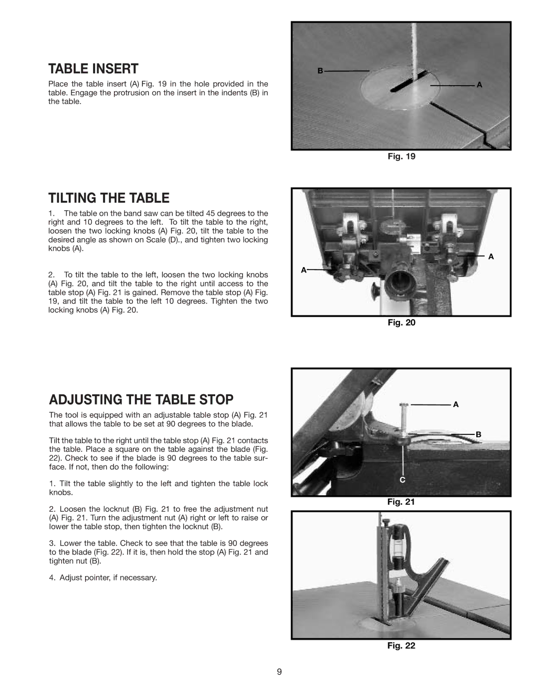
Place the table insert (A) Fig. 19 in the hole provided in the table. Engage the protrusion on the insert in the indents (B) in the table.
B
A
Fig. 19
TILTING THE TABLE
1.The table on the band saw can be tilted 45 degrees to the right and 10 degrees to the left. To tilt the table to the right, loosen the two locking knobs (A) Fig. 20, tilt the table to the desired angle as shown on Scale (D)., and tighten two locking knobs (A).
2.To tilt the table to the left, loosen the two locking knobs
(A) Fig. 20, and tilt the table to the right until access to the table stop (A) Fig. 21 is gained. Remove the table stop (A) Fig. 19, and tilt the table to the left 10 degrees. Tighten the two locking knobs (A) Fig. 20.
ADJUSTING THE TABLE STOP
The tool is equipped with an adjustable table stop (A) Fig. 21 that allows the table to be set at 90 degrees to the blade.
Tilt the table to the right until the table stop (A) Fig. 21 contacts the table. Place a square on the table against the blade (Fig. 22). Check to see if the blade is 90 degrees to the table sur- face. If not, then do the following:
1.Tilt the table slightly to the left and tighten the table lock knobs.
2.Loosen the locknut (B) Fig. 21 to free the adjustment nut
(A) Fig. 21. Turn the adjustment nut (A) right or left to raise or lower the table stop, then tighten the locknut (B).
3.Lower the table. Check to see that the table is 90 degrees to the blade (Fig. 22). If it is, then hold the stop (A) Fig. 21 and tighten nut (B).
4.Adjust pointer, if necessary.
A
A
Fig. 20
A
![]() B
B
C
Fig. 21
Fig. 22
9