OPERATING INSTRUCTIONS
FOREWORD
Delta Models
UNPACKING AND CLEANING
Carefully unpack the tool and all loose items from the shipping container(s). Remove the protective coating from all unpainted surfaces. This coating may be removed with a soft cloth moistened with kerosene (do not use acetone, gasoline or lacquer thinner for this purpose). After cleaning, cover the unpainted surfaces with a good quality household floor paste wax.
NOTICE: THE MANUAL COVER PHOTO ILLUSTRATES THE CURRENT PRODUCTION MODEL. ALL OTHER ILLUSTRATIONS ARE REPRESENTATIVE ONLY AND MAY NOT DEPICT THE ACTUAL COLOR, LABELING, OR ACCESSORIES.
ASSEMBLY
STAND
The stand is shipped
To make the motor operational, do the following:
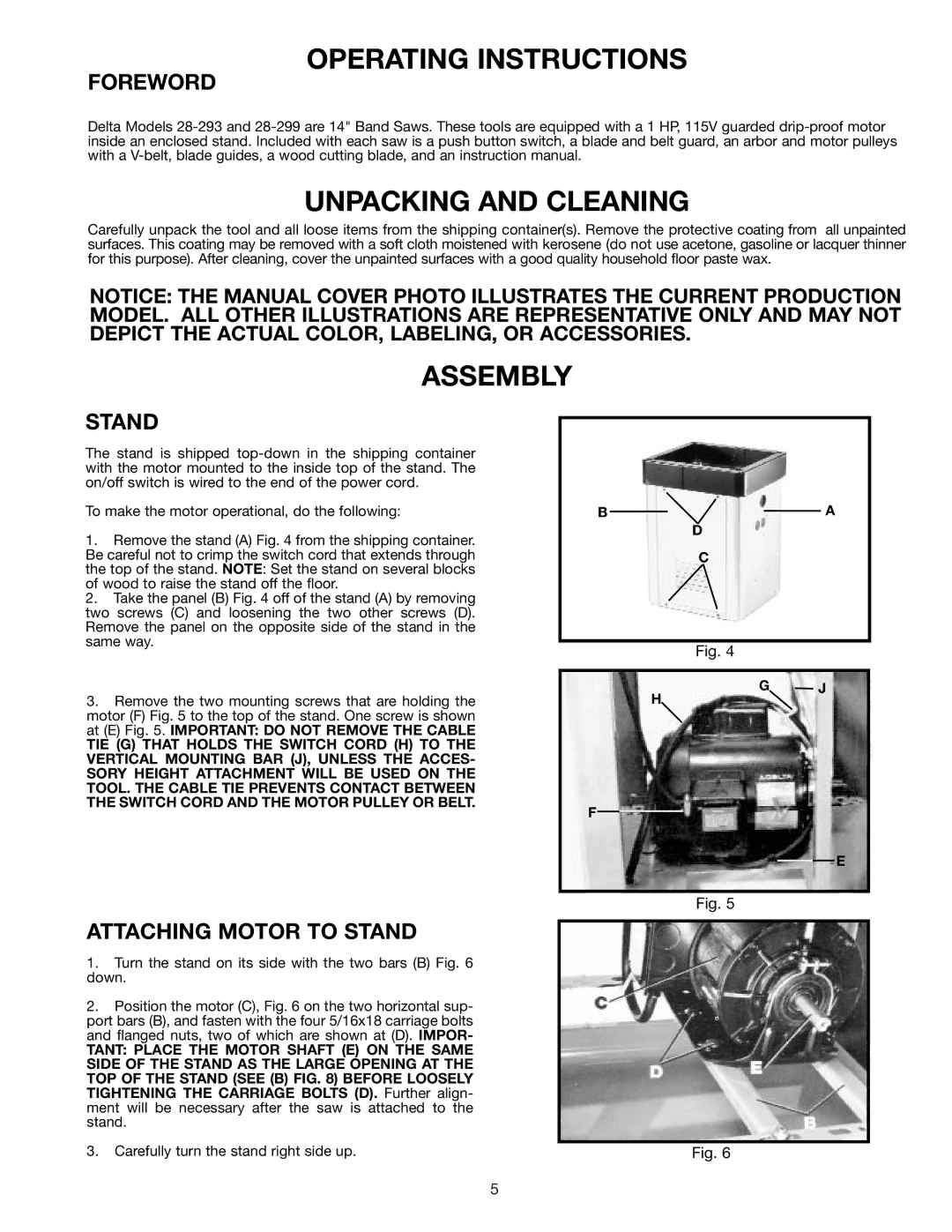
1.Remove the stand (A) Fig. 4 from the shipping container. Be careful not to crimp the switch cord that extends through the top of the stand. NOTE: Set the stand on several blocks of wood to raise the stand off the floor.
2.Take the panel (B) Fig. 4 off of the stand (A) by removing two screws (C) and loosening the two other screws (D). Remove the panel on the opposite side of the stand in the same way.
3.Remove the two mounting screws that are holding the motor (F) Fig. 5 to the top of the stand. One screw is shown at (E) Fig. 5. IMPORTANT: DO NOT REMOVE THE CABLE
TIE (G) THAT HOLDS THE SWITCH CORD (H) TO THE VERTICAL MOUNTING BAR (J), UNLESS THE ACCES- SORY HEIGHT ATTACHMENT WILL BE USED ON THE TOOL. THE CABLE TIE PREVENTS CONTACT BETWEEN THE SWITCH CORD AND THE MOTOR PULLEY OR BELT.
B ![]()
![]()
![]() A D
A D
C
Fig. 4
G J
H
F
E
ATTACHING MOTOR TO STAND
1.Turn the stand on its side with the two bars (B) Fig. 6 down.
2.Position the motor (C), Fig. 6 on the two horizontal sup- port bars (B), and fasten with the four 5/16x18 carriage bolts and flanged nuts, two of which are shown at (D). IMPOR-
TANT: PLACE THE MOTOR SHAFT (E) ON THE SAME SIDE OF THE STAND AS THE LARGE OPENING AT THE TOP OF THE STAND (SEE (B) FIG. 8) BEFORE LOOSELY TIGHTENING THE CARRIAGE BOLTS (D). Further align- ment will be necessary after the saw is attached to the stand.
3.Carefully turn the stand right side up.
Fig. 5
Fig. 6
5
