Euphonix MADI Converters Operation Manual | AM713 and MA703 Converters |
|
|
|
|
2.3AM713/MA703 Front Panel
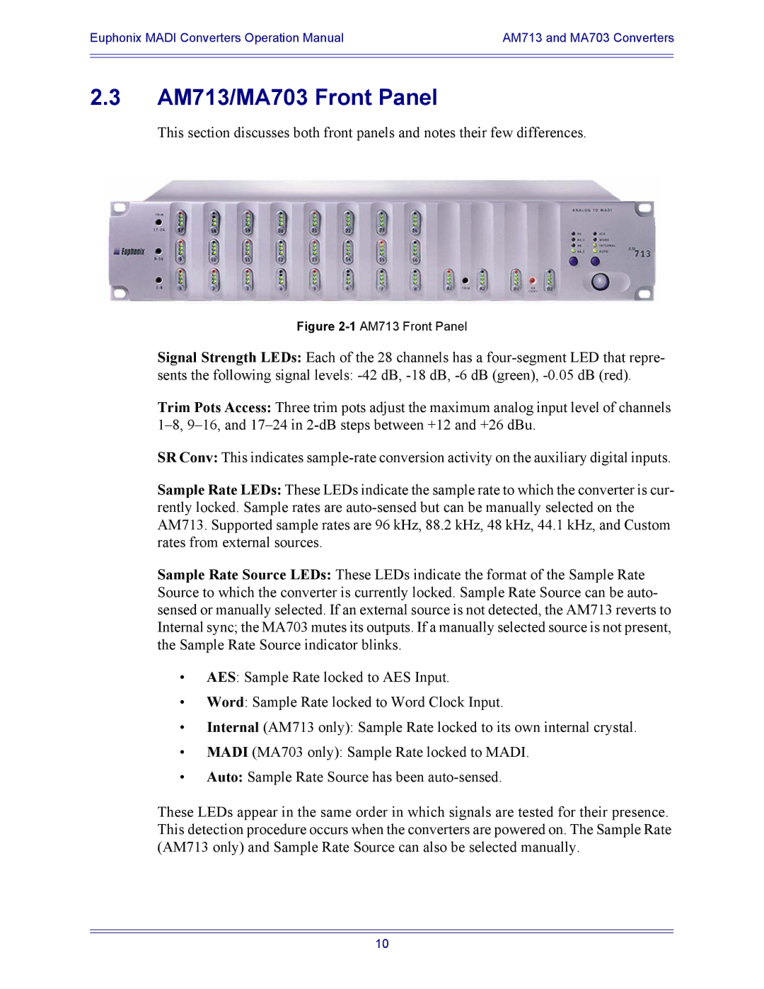
This section discusses both front panels and notes their few differences.
Figure 2-1 AM713 Front Panel
Signal Strength LEDs: Each of the 28 channels has a
sents the following signal levels:
Trim Pots Access: Three trim pots adjust the maximum analog input level of channels
SR Conv: This indicates
Sample Rate LEDs: These LEDs indicate the sample rate to which the converter is cur- rently locked. Sample rates are
Sample Rate Source LEDs: These LEDs indicate the format of the Sample Rate Source to which the converter is currently locked. Sample Rate Source can be auto- sensed or manually selected. If an external source is not detected, the AM713 reverts to Internal sync; the MA703 mutes its outputs. If a manually selected source is not present, the Sample Rate Source indicator blinks.
•AES: Sample Rate locked to AES Input.
•Word: Sample Rate locked to Word Clock Input.
•Internal (AM713 only): Sample Rate locked to its own internal crystal.
•MADI (MA703 only): Sample Rate locked to MADI.
•Auto: Sample Rate Source has been
These LEDs appear in the same order in which signals are tested for their presence. This detection procedure occurs when the converters are powered on. The Sample Rate (AM713 only) and Sample Rate Source can also be selected manually.
10