Euphonix MADI Converters Operation Manual | DM714 and MD704 Converters |
|
|
|
|
3.3DM 714/MD704 Front Panel
This section discusses both front panels and notes their few differences.
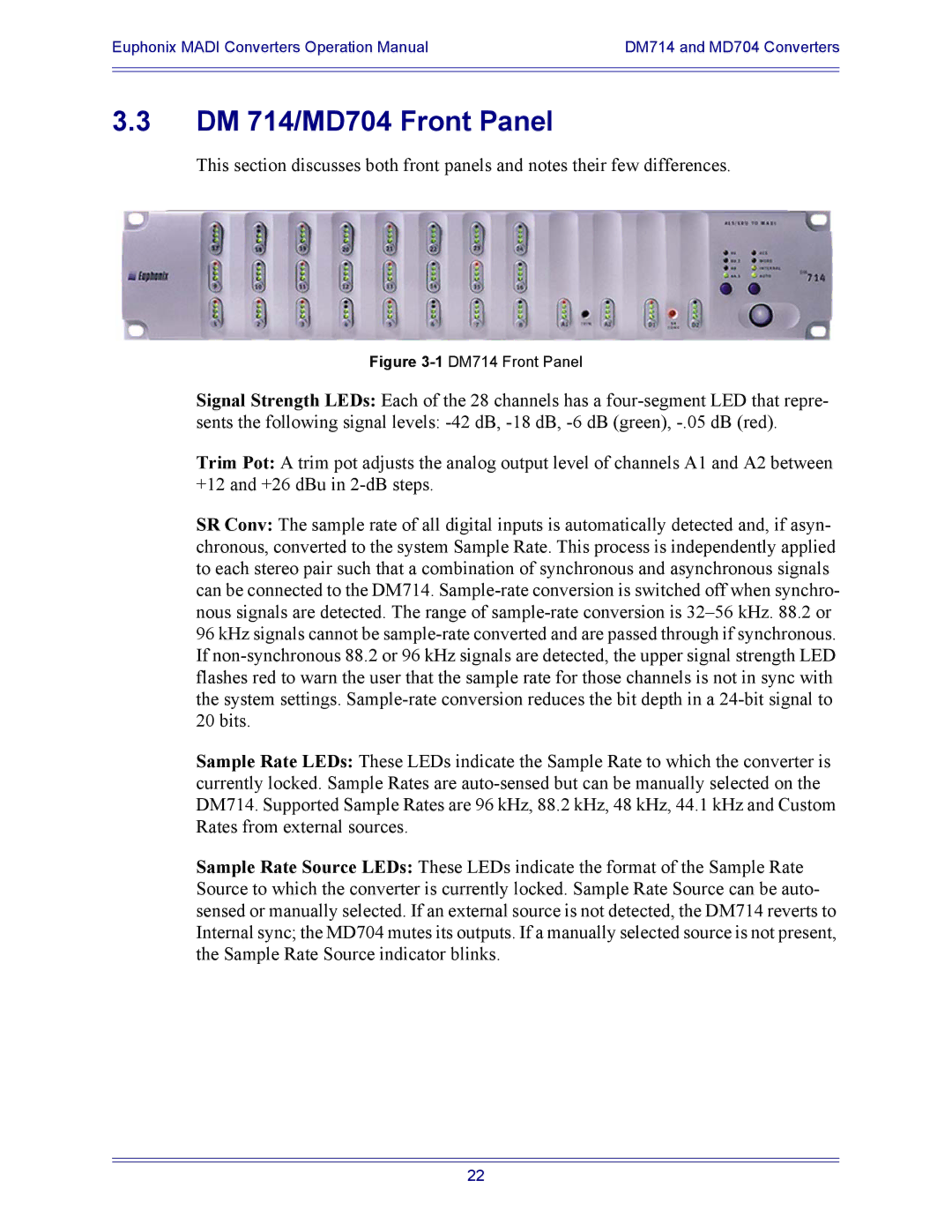
Figure 3-1 DM714 Front Panel
Signal Strength LEDs: Each of the 28 channels has a
sents the following signal levels:
Trim Pot: A trim pot adjusts the analog output level of channels A1 and A2 between +12 and +26 dBu in
SR Conv: The sample rate of all digital inputs is automatically detected and, if asyn- chronous, converted to the system Sample Rate. This process is independently applied to each stereo pair such that a combination of synchronous and asynchronous signals can be connected to the DM714.
Sample Rate LEDs: These LEDs indicate the Sample Rate to which the converter is currently locked. Sample Rates are
Sample Rate Source LEDs: These LEDs indicate the format of the Sample Rate Source to which the converter is currently locked. Sample Rate Source can be auto- sensed or manually selected. If an external source is not detected, the DM714 reverts to Internal sync; the MD704 mutes its outputs. If a manually selected source is not present, the Sample Rate Source indicator blinks.
22