Euphonix MADI Converters Operation Manual | DM714 and MD704 Converters |
|
|
|
|
3.5MD704 Rear Panel
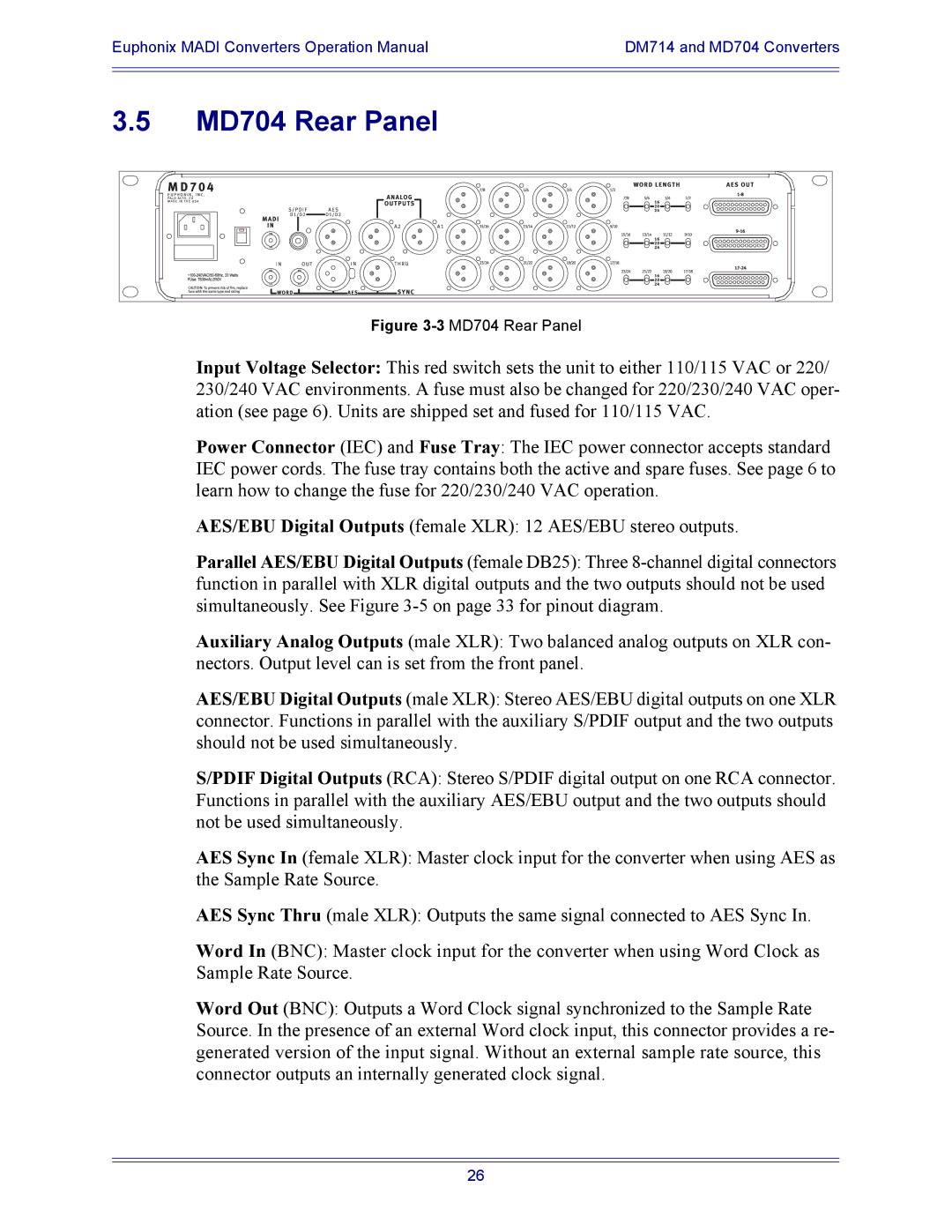
Figure 3-3 MD704 Rear Panel
Input Voltage Selector: This red switch sets the unit to either 110/115 VAC or 220/ 230/240 VAC environments. A fuse must also be changed for 220/230/240 VAC oper- ation (see page 6). Units are shipped set and fused for 110/115 VAC.
Power Connector (IEC) and Fuse Tray: The IEC power connector accepts standard IEC power cords. The fuse tray contains both the active and spare fuses. See page 6 to learn how to change the fuse for 220/230/240 VAC operation.
AES/EBU Digital Outputs (female XLR): 12 AES/EBU stereo outputs.
Parallel AES/EBU Digital Outputs (female DB25): Three
Auxiliary Analog Outputs (male XLR): Two balanced analog outputs on XLR con- nectors. Output level can is set from the front panel.
AES/EBU Digital Outputs (male XLR): Stereo AES/EBU digital outputs on one XLR connector. Functions in parallel with the auxiliary S/PDIF output and the two outputs should not be used simultaneously.
S/PDIF Digital Outputs (RCA): Stereo S/PDIF digital output on one RCA connector. Functions in parallel with the auxiliary AES/EBU output and the two outputs should not be used simultaneously.
AES Sync In (female XLR): Master clock input for the converter when using AES as the Sample Rate Source.
AES Sync Thru (male XLR): Outputs the same signal connected to AES Sync In.
Word In (BNC): Master clock input for the converter when using Word Clock as Sample Rate Source.
Word Out (BNC): Outputs a Word Clock signal synchronized to the Sample Rate Source. In the presence of an external Word clock input, this connector provides a re- generated version of the input signal. Without an external sample rate source, this connector outputs an internally generated clock signal.
26