2.3.1. Address Setting
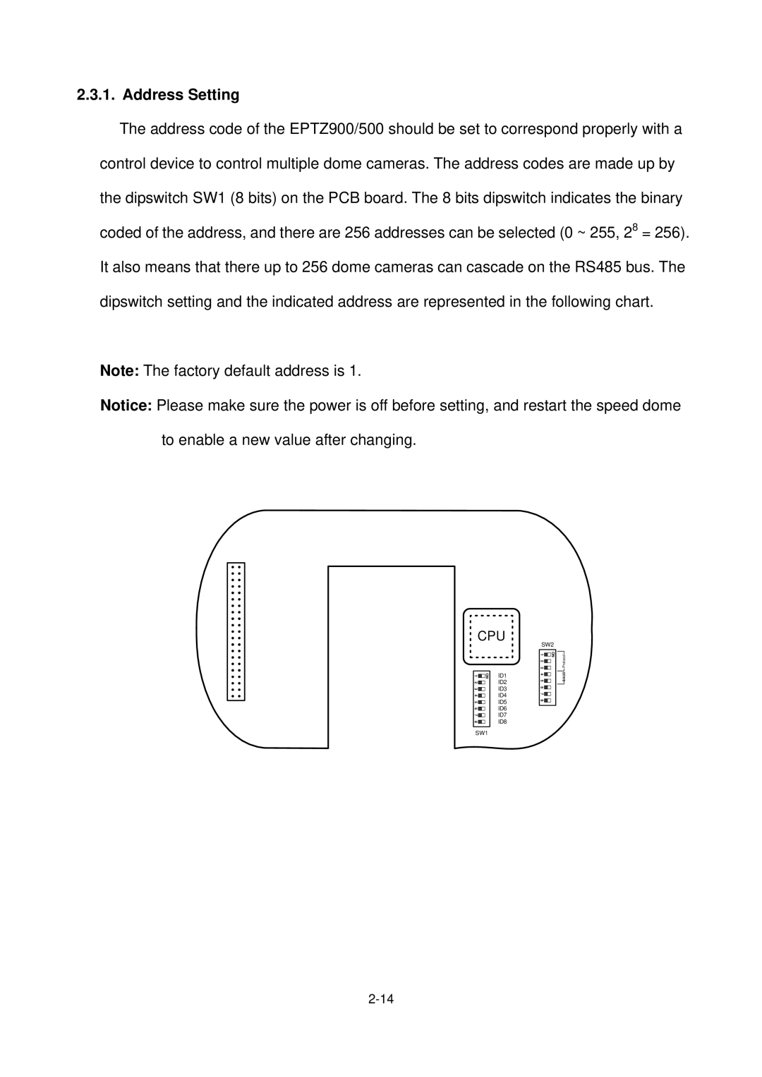
The address code of the EPTZ900/500 should be set to correspond properly with a control device to control multiple dome cameras. The address codes are made up by the dipswitch SW1 (8 bits) on the PCB board. The 8 bits dipswitch indicates the binary coded of the address, and there are 256 addresses can be selected (0 ~ 255, 28 = 256). It also means that there up to 256 dome cameras can cascade on the RS485 bus. The dipswitch setting and the indicated address are represented in the following chart.
Note: The factory default address is 1.
Notice: Please make sure the power is off before setting, and restart the speed dome to enable a new value after changing.
![]() CPU
CPU ![]()
1 | ON | ID1 |
| ||
2 |
| ID2 |
3 |
| ID3 |
4 |
| ID4 |
5 |
| ID5 |
6 |
| ID6 |
7 |
| ID7 |
8 |
| ID8 |
|
|
|
SW1
SW2
1 |
| ON |
2 |
| |
|
| |
3 |
|
|
4 |
|
|
5 |
|
|
6 |
|
|
7 |
|
|
8 |
|
|
|
|
|
BAUD Protocol
