53


FUSE BLOCK

FUEL SENDER


A

B


PTO SWITCH


IGNITION SWITCH


1

3

5

7

C


7

8

9


SEAT SWITCH


4 5


4


2

1


1


1

2

3


3 2


2

4

6

8


7 4 5 9 3 6 8 1 2

2 1


5 4 3 1 2


1 3 2 4 5 6 7 8


C A B

IGNITION SWITCH


PINK


BLACK


TERMINAL

CONNECTIONS

B


PINK


ORANGE


TERMINAL A

ACCESSORY

B


RED


TERMINAL B

BATTERY

A

A


PINK


PINK


VIOLET


TERMINAL I

IGNITION


1


ORANGE


BROWN


PINK


TERMINAL R

RECTIFIER

1

1


PINK


TERMINAL S

START

RH NEUTRAL

2


BROWN


GREEN


SWITCH


BROWN


2


LT.GREEN


BLACK


1

BLACK


GRAY


VIOLET


REGULATOR


TERMINAL I

LH NEUTRAL

1


RED


B+


SWITCH

2


TERMINAL A

2


MAG


TERMINAL R


FUEL SOLENOID


START


TERMINAL B


PINK


BLACK


1


BLACK


1


TERMINAL S

BRAKE

1

PINK


SWITCH

2


BLUE


2


POSITION

CIRCUIT "MAKE"


1. OFF

NONE


2. RUN

B + R + I + A

NOTE:


PINK

BROWN BLACK


PINK

ORANGE

ORANGE

RED VIOLET GRAY

GREEN BLACK

PINK BLUE

TAN

YELLOW

BROWN

WHITE


3. START

B + R + I + S

CONNECTORS VIEWED FROM MATING CONNECTOR


2 3 1 5 4

A B

A B


1

1


9 12 3 10 1 8 6 5 11 2 4 7


4


7

12


5

A B


ALARM

ALARM


3


A

B


2


TVS

(+)

PULSE


PTO


1

6


DIODE


CLUTCH


HOUR METER/MODULE


1


START RELAY


1

1

1

1

1

2

6

3

5

4

1

1

TERM (4)

TERM (2) TEMPERATURE

GAUGE

TERM (1)

TERM (3)

TEMP

SENDER

2

31

ENGINE

4 5 6

GROUND

G008588

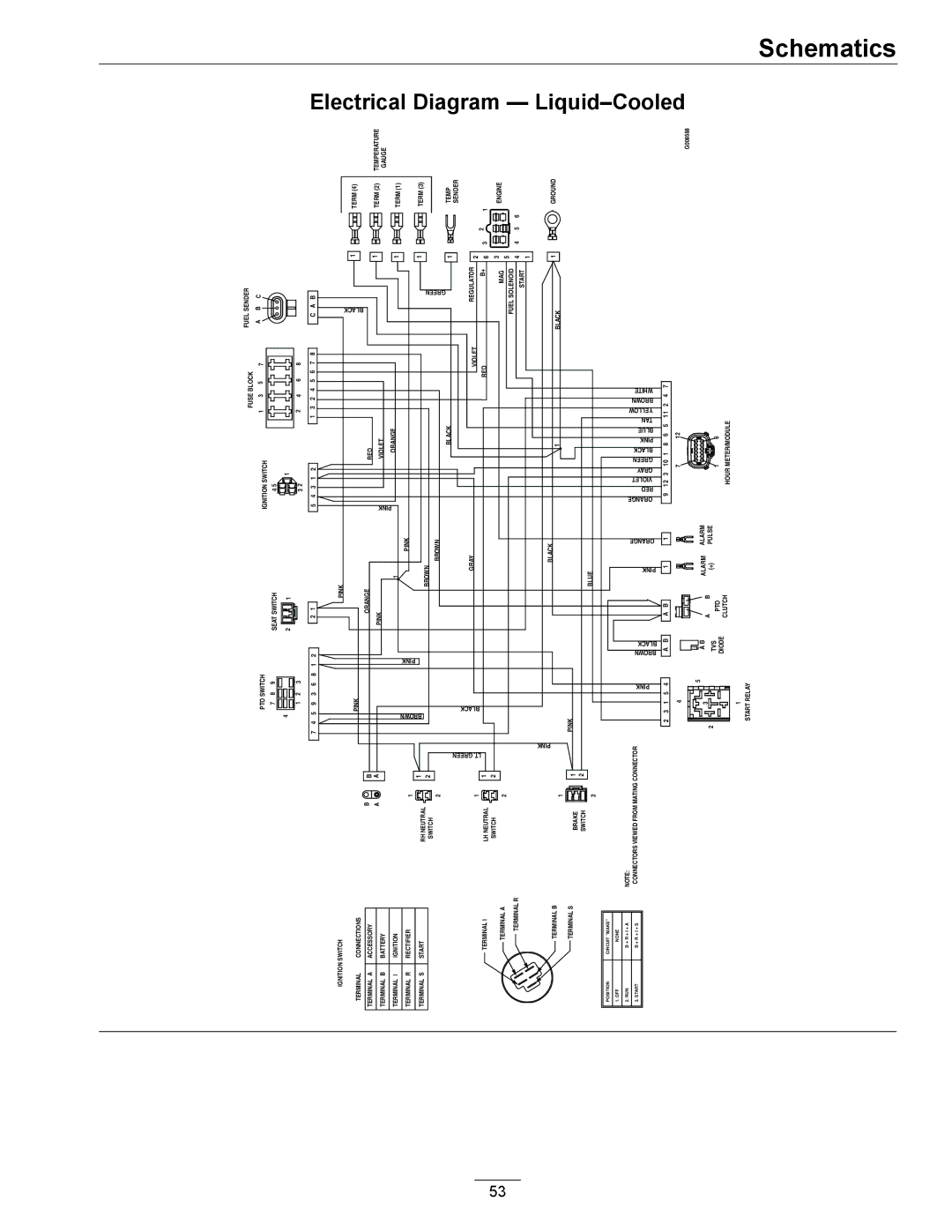
Electrical Diagram — Liquid–Cooled

Schematics

Page 53
Image 53
Exmark 000 & higher manual Electrical Diagram Liquid-Cooled, Tan

000 & higher specifications

Exmark has long been synonymous with excellence in the world of lawn care and landscaping, and their 000 & higher, 0,312 series is no exception. Engineered for both professional landscapers and passionate homeowners, this series brings together innovative technology with robust design to deliver unparalleled performance and durability.

One standout feature of this series is its powerful engine options, which ensure efficient cutting and grass handling capabilities. The engines are designed to provide consistent power and reliability, even in tough conditions. This reliability is complemented by high-quality cutting decks that deliver precision cuts and exceptional mulching abilities, ensuring that your lawn stays healthy and vibrant.

The cutting height adjustment system allows users to easily modify the height to suit various types of grass and landscaping needs. This adaptability ensures that your grass is always maintained at the optimal length for health and aesthetics. The ergonomic design of the handles incorporates comfort grips, reducing fatigue during prolonged use while providing excellent control over the machine.

Another significant aspect of the 000 & higher, 0,312 series is its advanced technology integration. Many models in this series come equipped with efficient fuel systems that enhance performance while minimizing fuel consumption. Furthermore, the inclusion of intelligent controls and monitoring systems enables users to make informed adjustments, ensuring that the equipment operates at peak performance.

The robust construction of the chassis and frame means that these machines can withstand the rigors of everyday use in various landscapes. The high-quality materials used in the manufacturing process enhance the longevity of the equipment, making it a worthy investment for those serious about maintaining their lawns.

In addition, Exmark places a strong emphasis on safety features. The series includes protective shields and easy-to-access controls that prioritize user safety without compromising on functionality. Maintenance is made simple through user-friendly designs, allowing for quick access to essential components.

In conclusion, the Exmark 000 & higher, 0,312 series presents a perfect blend of power, innovation, and user-focused features. With its reliable performance, flexible adjustment options, and sturdy design, this series continues to set the standard for excellence in lawn care equipment. Whether you’re a professional or a homeowner, the Exmark 000 & higher, 0,312 series stands ready to meet all your landscaping needs.