Revision September 22 Enterprise Platforms Group
STL2 Server Board
Date Revision Modifications Number
Revision History STL2 Server Board TPS
Table of Contents
Jumpers and Connectors
Basic Input Output System Bios
Table of ContentsSTL2 Server Board TPS
STL2 Server Board TPSTable of Contents
Power Consumption
List of Figures STL2 Server Board TPS
Embedded NIC PCI Signals
STL2 Server Board TPS List of Tables
List of Tables
List of TablesSTL2 Server Board TPS
Purpose
STL2 Server Board Feature Overview
Audience
STL2 Server Board TPS Introduction
Introduction STL2 Server Board TPS
STL2 Server Board Block Diagram
STL2 Server Board Block Diagram
This page intentionally left blank
Supported Processor Types
Intel Pentium III Processor Subsystem
STL2 Server Board Supported Processors
Speed FSB Frequency Cache Size Core
Dual Processor Operation
Processor Bus Termination / Regulation / Power
3 PGA370 Socket
Termination Package
Memory
ServerWorks ServerSet III LE Chipset
∙ NB6635 North Bridge 3.0LE
∙ IB6566 South Bridge
1 64-bit / 66 MHz PCI Subsystem
PCI I/O Subsystem
Ultra160 / Ultra WideSCSI Controller
Be 30 L Command Target Master
Embedded Scsi Supported PCI Commands
Scsi Transfer Speeds
AIC-7899 Support
Network Interface Controller NIC
2 32-bit/33 MHz PCI Subsystem
Supported Network Features
Video Controller
Video Controller PCI Signals
BE30L Command Type Target Master
Video Controller Supported PCI Commands
Resolution Refresh Rate Hz Colors
Standard VGA Modes
PCI Interface
2.3 IB6566 South Bridge
Chipset Support Components
Power Management
Legacy I/O Super I/O National* PC97317VUL
Compatibility Interrupt Control
Power Management Controller
Keyboard and Mouse Connectors
Serial Ports
Parallel Port
External Device Connectors
Bios Flash
Default I/O Apic
Interrupt Routing
STL2 Baseboard Interrupt Routing Diagram PIC mode
STL2 Baseboard Interrupt Routing Diagram Symmetric mode
PCI Ids
Device Bus Number Device Number Slot ID Signal 2316 1511
Relationship between PCI IRQ and PCI Device
STL2 PCI IDs
Revision
Page
STL2 Server Board TPS Server Management
Baseboard Management Controller
Server Management STL2 Server Board TPS
Hardware Sensors
Sensor Number Sensor Type Monitoring Device
Sensor Type Sensor-Specific Event Remarks Code Offset
PCI Serr
EMP
Acpi
Wake On LAN Function
AC Link Mode
STL2 Server Board TPS Basic Input Output System Bios
Bios Overview
Flash Update Utility
System Bios
Basic Input Output System Bios STL2 Server Board TPS
System Flash ROM Layout
Configuration Utilities Overview
Setup Utility
Setup Utility Operation
Setup Utility Screen
Keyboard Command Bar
Entering Setup Utility
Enter Execute Command
F1 Help
← → Select Menu
F9 Setup Defaults
F5/- Change Value
F6/+ Change Value
Main Menu Selections
Main Menu Selections
STL2 Server Board TPSBasic Input Output System Bios
Processor Settings Submenu Selections
Choices or Display Feature Only Description User Setting
Primary Master and Slave Adapters Submenu Selections
Advanced Menu Selections
Advanced Menu Selections
Memory Reconfiruation Submenu Selections
Peripheral Configuration Submenu Selections
Option ROM Submenu Selections
PCI Device Submenu Selections
10. Numlock Submenu Selections
11. Security Menu Selections
Security Menu Selections
System Hardware Menu Selections
12. Secure Mode Submenu Selections
13. Server Menu Selections
14. Wake On Events Submenu Selections
16. Boot Menu Selections
Boot Menu Selections
17. Boot Device Priority Selections
15. Console Redirection Submenu Selections
Exit Menu Selections
Cmos Memory Definition
18. Hard Drive Selections
19. Removable Devices Selections
Flash Update Utility
Cmos Default Override
Loading the System Bios
OEM Customization
User-supplied Bios Code Support
MSB
21. User Binary Area Scan Point Definitions
Scan Point Definitions
Scan Point Mask RAM/Stack/BDA Video/Keyboard
Language Area
Recovery Mode
OEM Splash Screen
22. Format of the User Binary Information Structure
Post Codes
Error Messages and Error Codes
23. Port-80h Code Definition
Code Meaning
Beeps Reason
24. Standard Bios Port-80 Codes
Page
Revision
25. Recovery Bios Port-80 Codes
Post Error Codes and Messages
26. Post Error Messages and Codes
Basic Input Output System BIOSSTL2 Server Board TPS
Revision
Beeps Error Cause Recommended Action
Bios Revision Level Identification
Identifying Bios and BMC Revision Levels
BMC Revision Level Identification
Adaptec Scsi Utility
Adaptec Scsi Utility Configuration Settings
Running the Scsi Utility
Bus Device Channel Selected Scsi Adapter
Option Recommended Setting or User Setting Display Only
27. Adaptec Scsi Utility Setup Configurations
Exiting Adaptec Scsi Utility
This page intentionally left blank
Page
STL2 Server Board TPS Jumpers and Connectors
Jumper and connector location key for Figure
Back Panel location key for Figure
Jumpers and Connectors STL2 Server Board TPS
Jumper Blocks
Setting CMOS/Password Clear Jumper Block 1J15
Jumper Block 1J15 Settings
Clearing and Changing a Password
Clearing Cmos
Setting Processor Frequency Jumper Block 5E1
Perfoming a Bios Recovery Boot
Jumper Block 5E1 Settings
Setting Configuration Jumper Block 1L4
Jumper Block 1J15 Default Settings
Setting Configuration Jumper Block 6A
Connectors
Jumper Block 1L4 Settings
Jumper Block 6A Settings
Auxilary ATX Power Connector P34
Main ATX Power Connector P33
3 I2C Power Connector P37
Processor Connectors P12, P36
System Fan Connectors P29, P27, P11
Speaker Connector P31
Speaker Connector P25
14. Video Port Connector Pinout
Diskette Drive Connector P20
Svga Video Port
Parallel Port
Keyboard and Mouse Connectors
Serial Ports COM1 and COM2
USB Connectors
13 RJ-45 LAN Connector
18. RJ-45 LAN Connector Signals
19. USB Connectors
Ultra160 Scsi Connector P8
Ultra Scsi Connector P9
20. Ultra Scsi Connector Pinout
21. Ultra160 Scsi Connector
22. IDE Connector Pinout
IDE Connector P19
Jumpers and Connectors STL2 Server Board TPS Pin Signal
23 -Bit PCI Connector Pinout
18 32-Bit PCI Connector
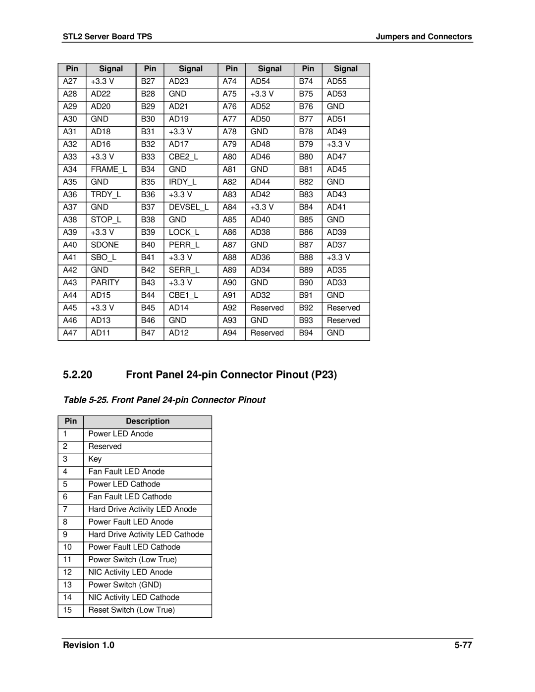
24 -Bit PCI Connctor Pinout
19 64-Bit PCI Connector
25. Front Panel 24-pin Connector Pinout
Front Panel 24-pin Connector Pinout P23
Pin Description
Jumpers and Connectors STL2 Server Board TPS
This page intentionally left blank
Page
STL2 Server Board Calculated Power Consumption
Calculated Power Consumption
STL2 Server Board Measured Power Consumption
Measured Power Consumption
Power Consumption STL2 Server Board TPS
Devices +5V +12V Total Wattage
STL2 Server Board TPS Mechanical Specifications
Mechanical Specifications
Mechanical Specifications STL2 Server Board TPS
Regulatory Compliance
Safety Regulations
Regulation Title
Ensure Host Computer and Accessory Module Certifications
Installation Instructions
Ensure EMC
Place Battery Marking on Computer
Prevent Power Supply Overload
Europe
United States
Environmental Limits
Installation Precautions
Use Only for Intended Applications
System Office Environment
System Environmental Testing
This page intentionally left blank
Term Definition
STL2 Server Board TPS Glossary
Reference Documents STL2 Server Board TPS
Reference Documents