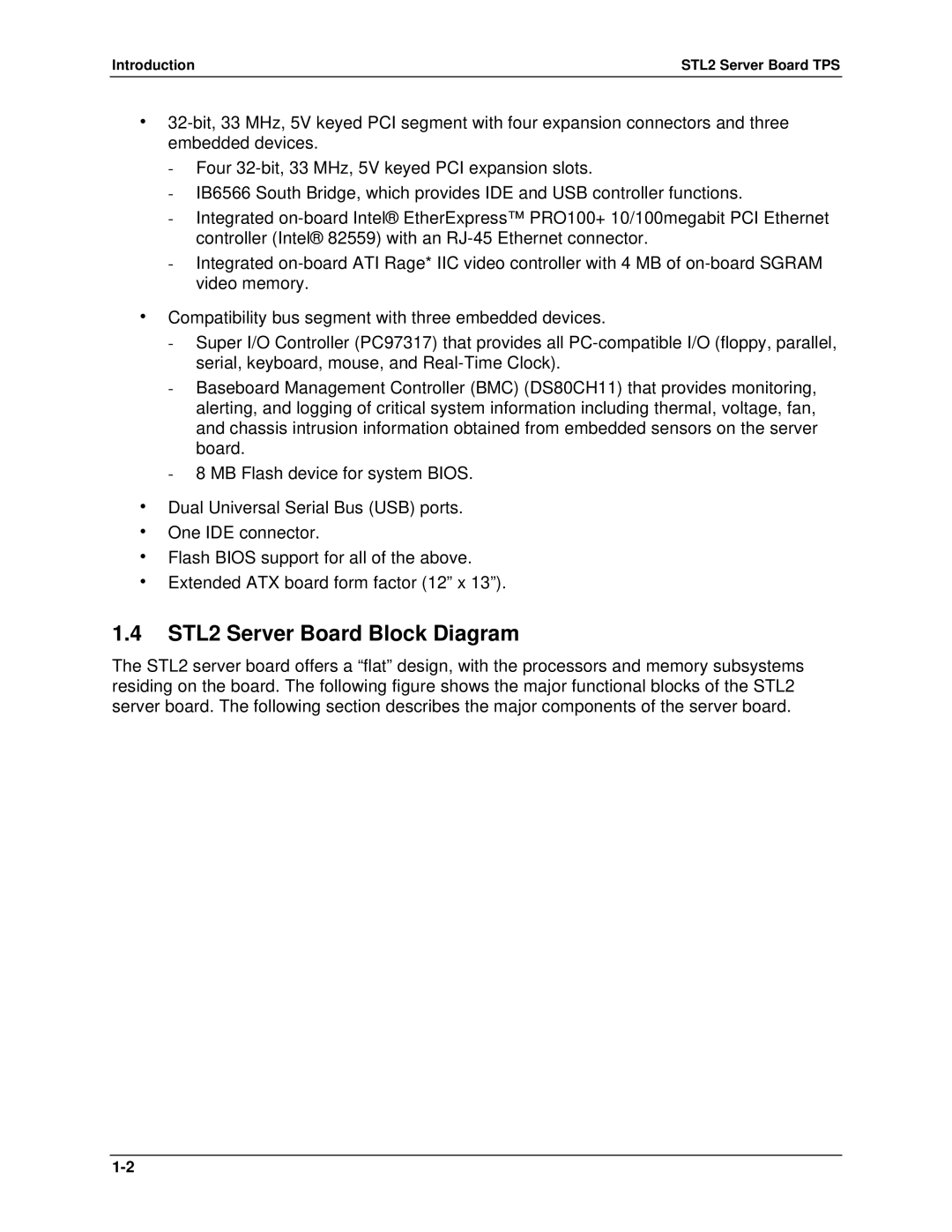
STL2 specifications
The Intel STL2, known as the Intel Storage Technology Level 2, is a robust solution designed to elevate storage management and performance for enterprise-level applications. This next-generation system is specifically tailored for organizations that demand high reliability, scalability, and efficiency in their storage solutions.One of the primary features of the Intel STL2 is its advanced data protection mechanisms. With integrated RAID (Redundant Array of Independent Disks) support, it ensures that data remains safe, even in the event of hardware failure. RAID configurations can be easily set up and managed, allowing businesses to choose the right balance between performance and redundancy based on their unique requirements.
In terms of performance, the STL2 leverages cutting-edge SSD (Solid State Drive) integration to provide high-speed data access and reduced latency. This capability is essential for modern applications that require quick retrieval of large volumes of data, making it suitable for environments like data analytics, AI, and cloud computing.
Scalability is another significant characteristic of the Intel STL2. It is designed to grow alongside an organization’s needs, supporting a diverse range of storage architectures. Whether a company is looking to expand its data center or transition to hybrid cloud solutions, the STL2 can accommodate additional storage resources effortlessly, ensuring that performance does not degrade as storage demands increase.
Moreover, the STL2 features advanced automation and management tools that simplify storage operations. The system allows for real-time monitoring and analytics, providing insights into storage health, performance metrics, and capacity forecasts. This level of visibility enables IT teams to optimize resource utilization and proactively address potential issues before they become critical.
Another notable technology integrated into the STL2 is Intel’s Open Storage Architecture, which promotes interoperability with various software and hardware platforms. This open approach facilitates seamless integrations with existing systems and enhances flexibility within dynamic IT environments.
Lastly, Intel STL2 prioritizes energy efficiency. Its design minimizes power consumption without sacrificing performance, helping organizations reduce their operational costs and carbon footprint.
In summary, the Intel STL2 stands out in the competitive landscape of storage solutions with its focus on data protection, high performance, scalability, advanced management features, open architecture compatibility, and energy efficiency. These characteristics make it an ideal choice for businesses looking to enhance their data storage capabilities in a rapidly evolving digital landscape.
