Safety
Safety and Instructional Decals
•Keep all safety signs legible. Remove all grease, dirt and debris from safety signs and instructional labels.
•Replace all worn, damaged, or missing safety signs.
•When replacement components are installed, be sure that current safety signs are affixed to the replaced components.
•If an attachment or accessory has been installed, make sure current safety signs are visible.
•New safety signs may be obtained from your authorized Exmark equipment dealer or distributor or from Exmark Mfg. Co. Inc.
•Safety signs may be affixed by peeling off the backing to expose the adhesive surface. Apply only to a clean, dry surface. Smooth to remove any air bubbles.
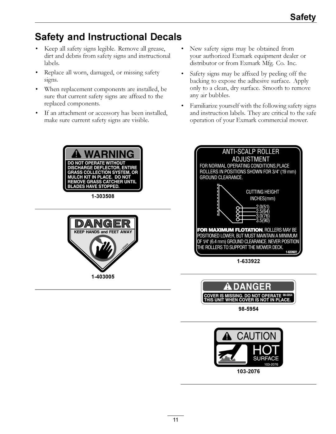
•Familiarize yourself with the following safety signs and instruction labels. They are critical to the safe operation of your Exmark commercial mower.
11