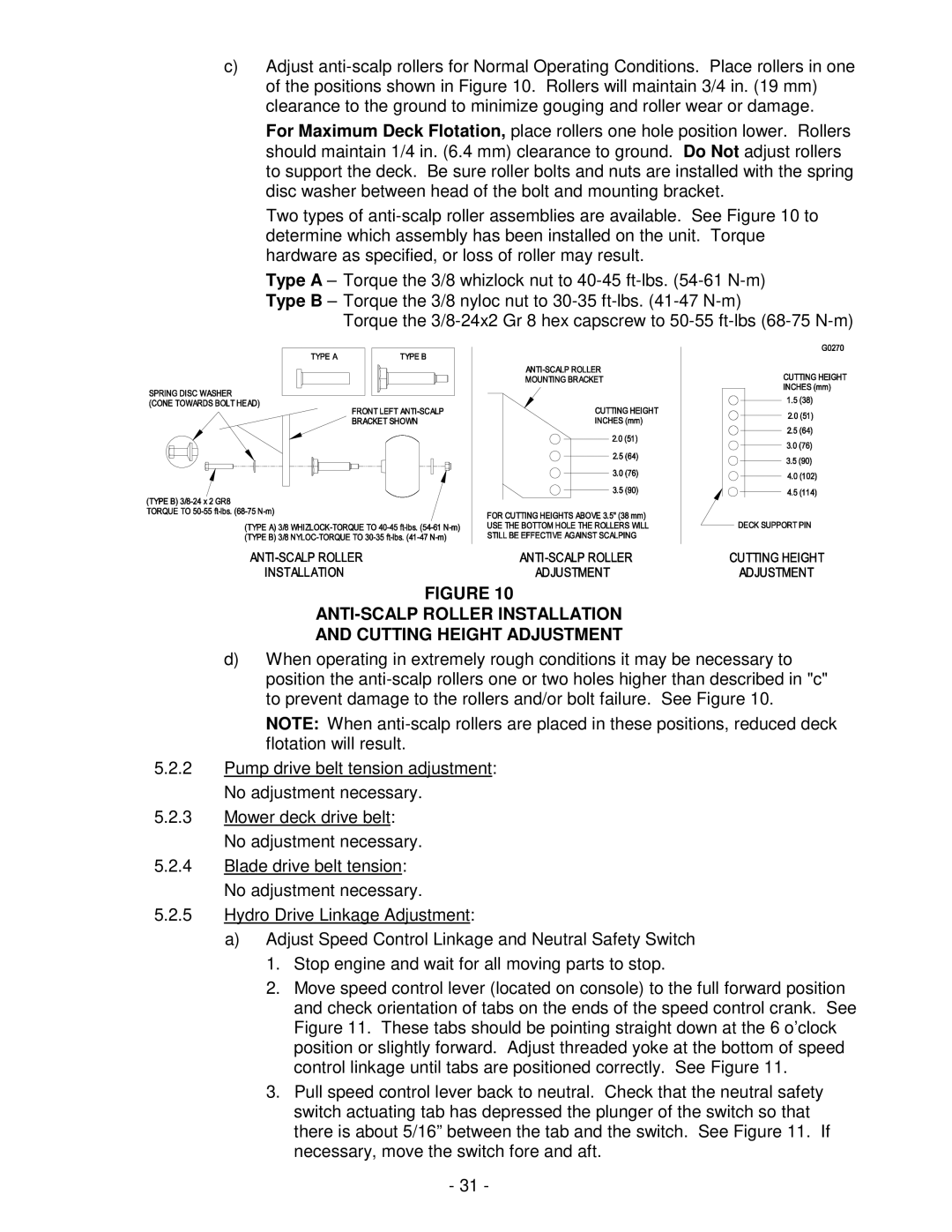
c)Adjust
For Maximum Deck Flotation, place rollers one hole position lower. Rollers should maintain 1/4 in. (6.4 mm) clearance to ground. Do Not adjust rollers to support the deck. Be sure roller bolts and nuts are installed with the spring disc washer between head of the bolt and mounting bracket.
Two types of
Type A – Torque the 3/8 whizlock nut to
Torque the
FIGURE 10
ANTI-SCALP ROLLER INSTALLATION
AND CUTTING HEIGHT ADJUSTMENT
d)When operating in extremely rough conditions it may be necessary to position the
NOTE: When
5.2.2Pump drive belt tension adjustment: No adjustment necessary.
5.2.3Mower deck drive belt: No adjustment necessary.
5.2.4Blade drive belt tension: No adjustment necessary.
5.2.5Hydro Drive Linkage Adjustment:
a)Adjust Speed Control Linkage and Neutral Safety Switch
1.Stop engine and wait for all moving parts to stop.
2.Move speed control lever (located on console) to the full forward position and check orientation of tabs on the ends of the speed control crank. See Figure 11. These tabs should be pointing straight down at the 6 o’clock position or slightly forward. Adjust threaded yoke at the bottom of speed control linkage until tabs are positioned correctly. See Figure 11.
3.Pull speed control lever back to neutral. Check that the neutral safety switch actuating tab has depressed the plunger of the switch so that there is about 5/16” between the tab and the switch. See Figure 11. If necessary, move the switch fore and aft.
-31 -
