e)Move lever out of transport (or 5” (12.7 cm) cutting height) position and down onto height adjustment pin to mow at selected height.
f)To transport, move lever back up to transport (or 5” (12.7 cm) cutting height) position.
Note: The foot operated deck lift assist lever can be used to momentarily lift the deck to clear objects. Be sure that PTO is disengaged.
g)Adjust
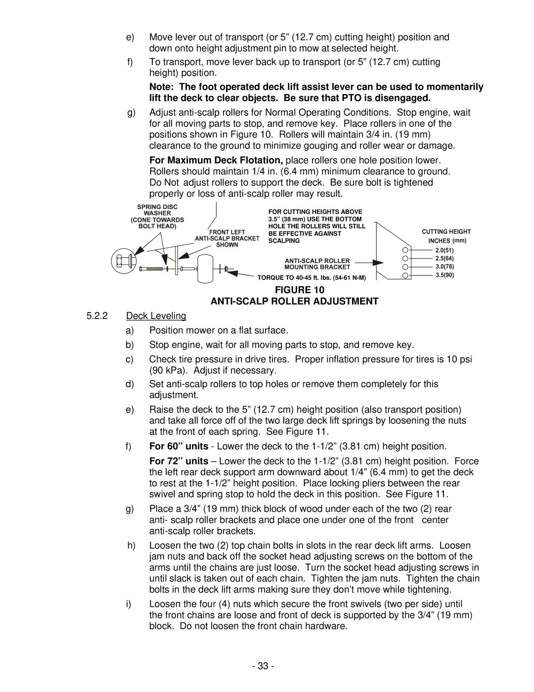
For Maximum Deck Flotation, place rollers one hole position lower. Rollers should maintain 1/4 in. (6.4 mm) minimum clearance to ground. Do Not adjust rollers to support the deck. Be sure bolt is tightened properly or loss of
FOR CUTTING HEIGHTS ABOVE 3.5” (38 mm) USE THE BOTTOM
HOLE THE ROLLERS WILL STILL BE EFFECTIVE AGAINST ![]()
![]()
![]() SCALPING
SCALPING ![]()
![]()
![]()
![]()
![]()
![]()
![]()
![]()
![]()
![]()
![]() TORQUE TO
TORQUE TO
FIGURE 10
ANTI-SCALP ROLLER ADJUSTMENT
5.2.2Deck Leveling
a)Position mower on a flat surface.
b)Stop engine, wait for all moving parts to stop, and remove key.
c)Check tire pressure in drive tires. Proper inflation pressure for tires is 10 psi (90 kPa). Adjust if necessary.
d)Set
e)Raise the deck to the 5” (12.7 cm) height position (also transport position) and take all force off of the two large deck lift springs by loosening the nuts at the front of each spring. See Figure 11.
f)For 60” units - Lower the deck to the
For 72” units – Lower the deck to the
g)Place a 3/4” (19 mm) thick block of wood under each of the two (2) rear anti- scalp roller brackets and place one under one of the front center
h)Loosen the two (2) top chain bolts in slots in the rear deck lift arms. Loosen jam nuts and back off the socket head adjusting screws on the bottom of the arms until the chains are just loose. Turn the socket head adjusting screws in until slack is taken out of each chain. Tighten the jam nuts. Tighten the chain bolts in the deck lift arms making sure they don’t move while tightening.
i)Loosen the four (4) nuts which secure the front swivels (two per side) until the front chains are loose and front of deck is supported by the 3/4” (19 mm) block. Do not loosen the front chain hardware.
- 33 -