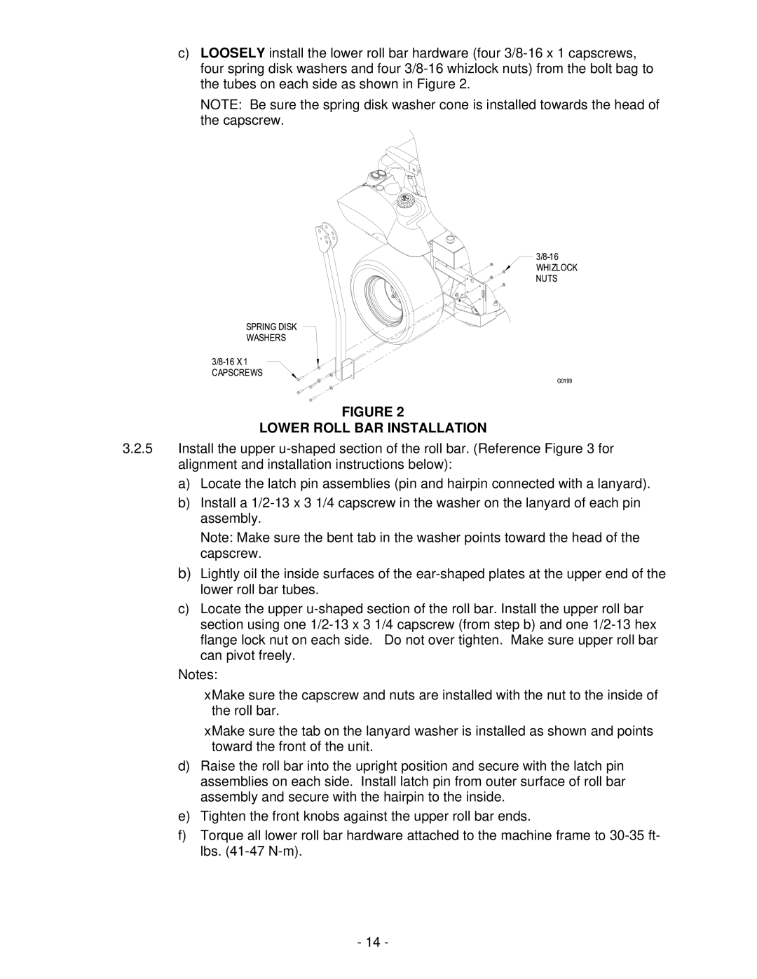
c)LOOSELY install the lower roll bar hardware (four
NOTE: Be sure the spring disk washer cone is installed towards the head of the capscrew.
FIGURE 2
LOWER ROLL BAR INSTALLATION
3.2.5Install the upper
a)Locate the latch pin assemblies (pin and hairpin connected with a lanyard).
b)Install a
Note: Make sure the bent tab in the washer points toward the head of the capscrew.
b)Lightly oil the inside surfaces of the
c)Locate the upper
Notes:
•Make sure the capscrew and nuts are installed with the nut to the inside of the roll bar.
•Make sure the tab on the lanyard washer is installed as shown and points toward the front of the unit.
d)Raise the roll bar into the upright position and secure with the latch pin assemblies on each side. Install latch pin from outer surface of roll bar assembly and secure with the hairpin to the inside.
e)Tighten the front knobs against the upper roll bar ends.
f)Torque all lower roll bar hardware attached to the machine frame to
- 14 -
