Installation, cont’d

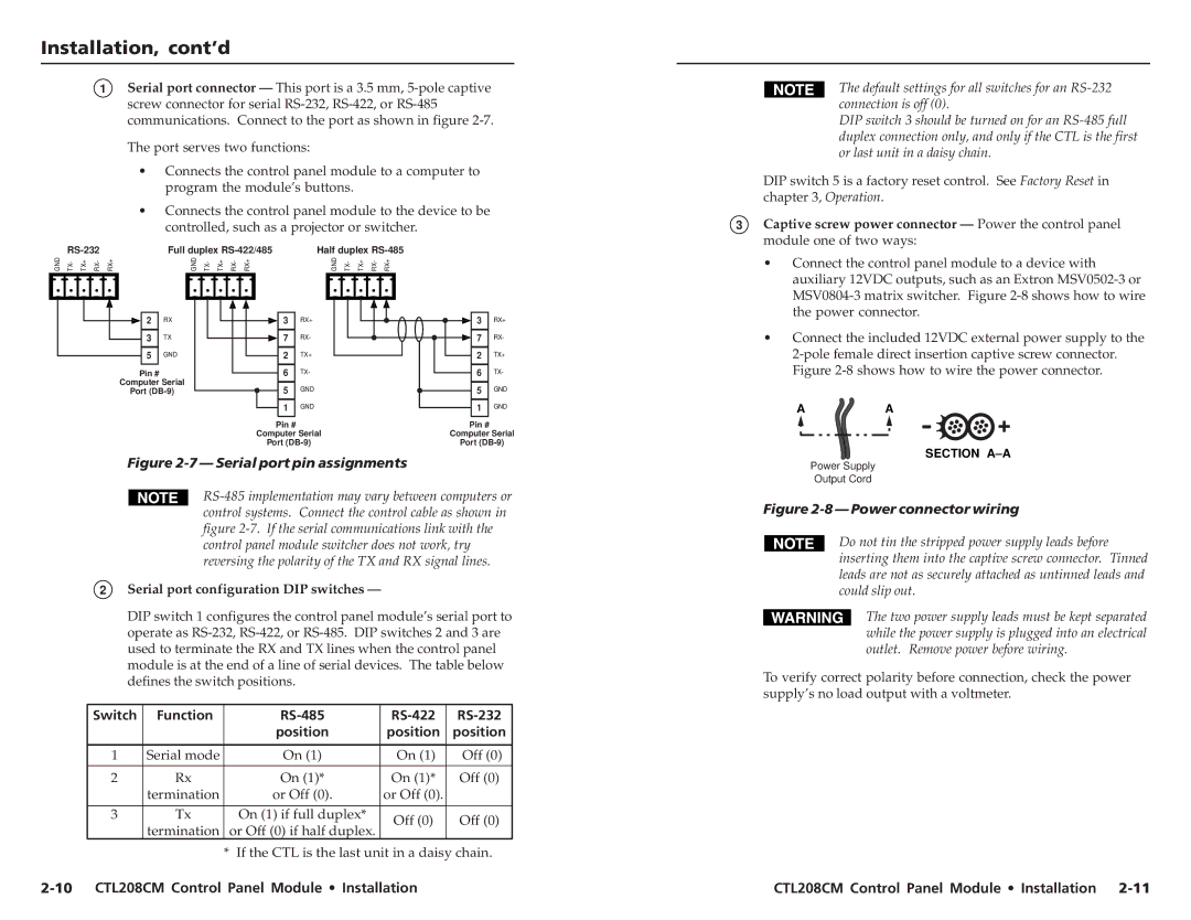
1Serial port connector — This port is a 3.5 mm, 5-pole captive screw connector for serial RS-232, RS-422, or RS-485 communications. Connect to the port as shown in figure 2-7.

The port serves two functions:

Connects the control panel module to a computer to program the module’s buttons.

Connects the control panel module to the device to be controlled, such as a projector or switcher.


RS-232


Full duplex RS-422/485

Half duplex RS-485

GND

TX-

TX+

RX-

RX+


GND

TX-

TX+

RX-

RX+


GND

TX-

TX+

RX-

RX+


The default settings for all switches for an RS-232 connection is off (0).

DIP switch 3 should be turned on for an RS-485 full duplex connection only, and only if the CTL is the first or last unit in a daisy chain.

DIP switch 5 is a factory reset control. See Factory Reset in chapter 3, Operation.

3 Captive screw power connector — Power the control panel

module one of two ways:

• Connect the control panel module to a device with

auxiliary 12VDC outputs, such as an Extron MSV0502-3 or

MSV0804-3 matrix switcher. Figure 2-8 shows how to wire

2 RX

3

TX

5

GND

Pin #

Computer Serial

Port (DB-9)

3

RX+

7

RX-

2

TX+

6

TX-

5

GND

1 GND

Pin #

Computer Serial

Port (DB-9)

3

RX+

7

RX-

2

TX+

6

TX-

5

GND

1 GND

Pin #

Computer Serial

Port (DB-9)

the power connector.

• Connect the included 12VDC external power supply to the

2-pole female direct insertion captive screw connector.

Figure 2-8 shows how to wire the power connector.

AA

Figure 2-7 — Serial port pin assignments

RS-485 implementation may vary between computers or control systems. Connect the control cable as shown in figure 2-7. If the serial communications link with the control panel module switcher does not work, try reversing the polarity of the TX and RX signal lines.

2Serial port configuration DIP switches —

DIP switch 1 configures the control panel module’s serial port to operate as RS-232, RS-422, or RS-485. DIP switches 2 and 3 are used to terminate the RX and TX lines when the control panel module is at the end of a line of serial devices. The table below defines the switch positions.

Switch

Function


RS-485

RS-422

RS-232


position

position

position


1

Serial mode


On (1)

On (1)

Off (0)


2

Rx


On (1)*

On (1)*

Off (0)


termination


or Off (0).

or Off (0).


3

Tx


On (1) if full duplex*

Off (0)

Off (0)


termination


or Off (0) if half duplex.


*

If the CTL is the last unit in a daisy chain.

2-10 CTL208CM Control Panel Module • Installation

SECTION A–A

Power Supply

Output Cord

Figure 2-8 — Power connector wiring

Do not tin the stripped power supply leads before inserting them into the captive screw connector. Tinned leads are not as securely attached as untinned leads and could slip out.

The two power supply leads must be kept separated while the power supply is plugged into an electrical outlet. Remove power before wiring.

To verify correct polarity before connection, check the power supply’s no load output with a voltmeter.

CTL208CM Control Panel Module • Installation 2-11

Page 12
Image 12
Extron electronic 10 CTL208CM Control Panel Module Installation, Captive screw power connector Power the control panel

CTL208CM specifications

The Extron CTL 208 CM is a sophisticated control system designed for seamless integration and management of AV systems in various environments, such as educational institutions, corporate spaces, and any setting requiring robust audiovisual control. Known for its user-friendly interface and advanced features, the CTL 208 CM stands out in its category.

One of the primary features of the CTL 208 CM is its ability to control multiple AV devices through a single platform. This centralized control facilitates ease of operation for users, allowing them to manage projectors, displays, sound systems, and other devices without the need to juggle multiple remotes or interfaces. This is particularly beneficial in environments where educators or presenters need to focus on delivering their content without getting bogged down by technicalities.

The CTL 208 CM is equipped with Extron’s proprietary technologies, which enhance its performance and reliability. Notable among these is the Extron Control App, which allows users to create custom controls via a tablet or smartphone. This not only streamlines the user experience but also enables personalized settings, ensuring users can quickly access the devices they need.

Additionally, the CTL 208 CM features customizable button layouts and a graphic interface that simplifies operation, regardless of the user's technical proficiency. This flexibility is crucial in environments where users may vary significantly in their comfort level with technology.

The system's advanced communication capabilities enable it to integrate seamlessly with a variety of third-party devices, expanding its functionality and compatibility. This open architecture design supports popular protocols such as RS-232, IP control, and infrared, allowing users to implement it alongside existing infrastructures effectively.

Moreover, the CTL 208 CM boasts a scalable architecture, making it suitable for small to large installations. Users can easily expand their control system as their needs evolve without requiring a complete overhaul of their existing setup.

In summary, the Extron CTL 208 CM is a powerful control solution that combines ease of use with extensive functionality. Its advanced technologies and features position it as an ideal choice for anyone seeking a reliable and versatile AV control system. With its ability to simplify AV management and enhance user engagement, the CTL 208 CM is a valuable asset for modern audiovisual environments.