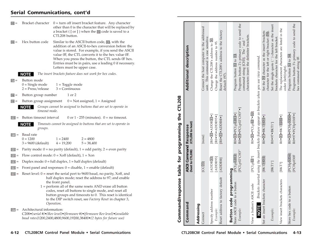
CTL208CM specifications
The Extron CTL 208 CM is a sophisticated control system designed for seamless integration and management of AV systems in various environments, such as educational institutions, corporate spaces, and any setting requiring robust audiovisual control. Known for its user-friendly interface and advanced features, the CTL 208 CM stands out in its category.One of the primary features of the CTL 208 CM is its ability to control multiple AV devices through a single platform. This centralized control facilitates ease of operation for users, allowing them to manage projectors, displays, sound systems, and other devices without the need to juggle multiple remotes or interfaces. This is particularly beneficial in environments where educators or presenters need to focus on delivering their content without getting bogged down by technicalities.
The CTL 208 CM is equipped with Extron’s proprietary technologies, which enhance its performance and reliability. Notable among these is the Extron Control App, which allows users to create custom controls via a tablet or smartphone. This not only streamlines the user experience but also enables personalized settings, ensuring users can quickly access the devices they need.
Additionally, the CTL 208 CM features customizable button layouts and a graphic interface that simplifies operation, regardless of the user's technical proficiency. This flexibility is crucial in environments where users may vary significantly in their comfort level with technology.
The system's advanced communication capabilities enable it to integrate seamlessly with a variety of third-party devices, expanding its functionality and compatibility. This open architecture design supports popular protocols such as RS-232, IP control, and infrared, allowing users to implement it alongside existing infrastructures effectively.
Moreover, the CTL 208 CM boasts a scalable architecture, making it suitable for small to large installations. Users can easily expand their control system as their needs evolve without requiring a complete overhaul of their existing setup.
In summary, the Extron CTL 208 CM is a powerful control solution that combines ease of use with extensive functionality. Its advanced technologies and features position it as an ideal choice for anyone seeking a reliable and versatile AV control system. With its ability to simplify AV management and enhance user engagement, the CTL 208 CM is a valuable asset for modern audiovisual environments.


