Installation and Operation, cont’d

TP Cable (no boot)

TP Cable (no boot)

Captive

Screw

Connectors

2.50” [63.5mm]

1.51” [38.48mm]

Wall Stud

Wall Stud

Signal

Signal

Output

Output

Cable

Cable


Cable

Cable

Clamp

Clamp

Screws

Screws

or Nails

or Nails


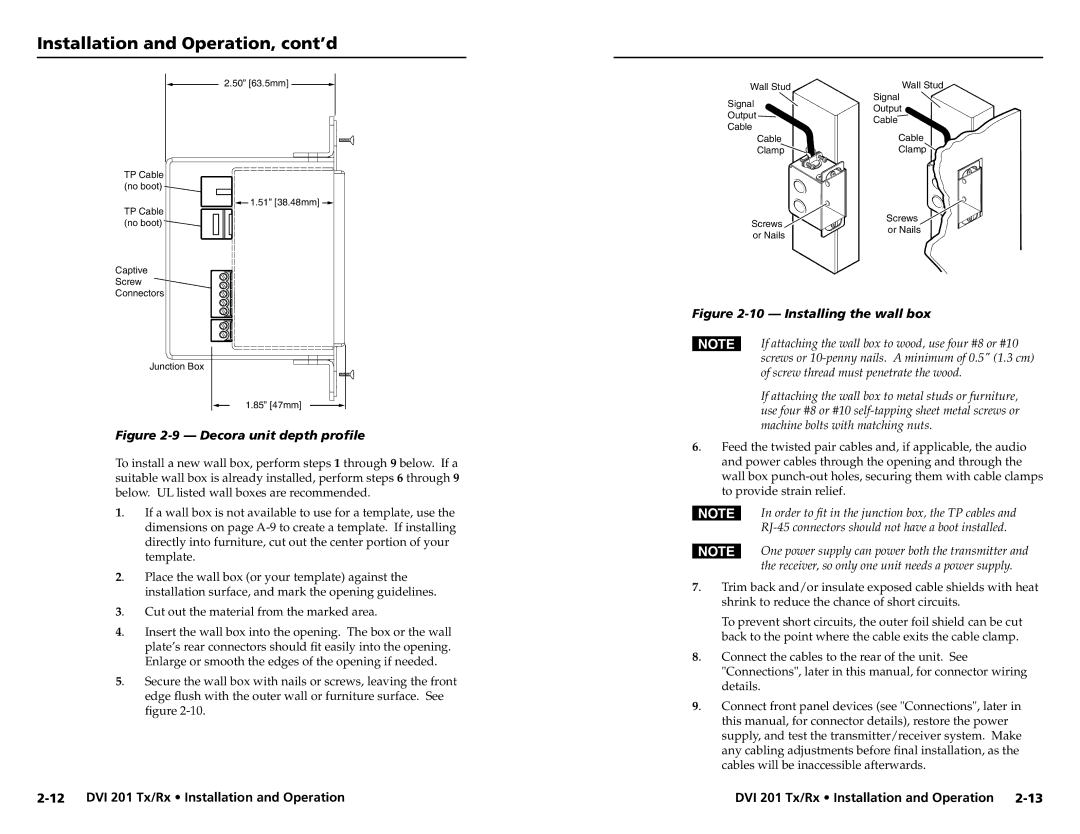
Figure 2-10 — Installing the wall box

Junction Box

1.85” [47mm]

Figure 2-9 — Decora unit depth profile

To install a new wall box, perform steps 1 through 9 below. If a suitable wall box is already installed, perform steps 6 through 9 below. UL listed wall boxes are recommended.

1. If a wall box is not available to use for a template, use the dimensions on page A-9 to create a template. If installing directly into furniture, cut out the center portion of your template.

2. Place the wall box (or your template) against the installation surface, and mark the opening guidelines.

3. Cut out the material from the marked area.

4. Insert the wall box into the opening. The box or the wall plate’s rear connectors should fit easily into the opening. Enlarge or smooth the edges of the opening if needed.

5. Secure the wall box with nails or screws, leaving the front edge flush with the outer wall or furniture surface. See figure 2-10.

NIf attaching the wall box to wood, use four #8 or #10 screws or 10-penny nails. A minimum of 0.5" (1.3 cm) of screw thread must penetrate the wood.

If attaching the wall box to metal studs or furniture, use four #8 or #10 self-tapping sheet metal screws or machine bolts with matching nuts.

6. Feed the twisted pair cables and, if applicable, the audio and power cables through the opening and through the wall box punch-out holes, securing them with cable clamps to provide strain relief.

NIn order to fit in the junction box, the TP cables and RJ-45 connectors should not have a boot installed.

NOne power supply can power both the transmitter and the receiver, so only one unit needs a power supply.

7. Trim back and/or insulate exposed cable shields with heat shrink to reduce the chance of short circuits.

To prevent short circuits, the outer foil shield can be cut back to the point where the cable exits the cable clamp.

8. Connect the cables to the rear of the unit. See "Connections", later in this manual, for connector wiring details.

9. Connect front panel devices (see "Connections", later in this manual, for connector details), restore the power supply, and test the transmitter/receiver system. Make any cabling adjustments before final installation, as the cables will be inaccessible afterwards.

2-12 DVI 201 Tx/Rx • Installation and Operation

DVI 201 Tx/Rx • Installation and Operation 2-13

Page 14
Image 14
Extron electronic DVI 201 Tx, DVI 201 Rx user manual Installing the wall box

DVI 201 Tx, DVI 201 Rx specifications

Extron Electronics is known for its innovative solutions in the field of professional AV signal distribution and extension. Among its robust product lineup are the DVI 201 Rx and DVI 201 Tx devices, which are essential for transmitting and receiving digital video signals with exceptional performance and reliability.

The Extron DVI 201 Tx is a DVI transmitter that seamlessly converts DVI signals to a format suitable for long-distance transmission. It features a DVI connector for input and utilizes advanced technologies to ensure minimal signal degradation. The DVI 201 Tx supports high-resolution video up to 1920x1200 at 60 Hz, making it ideal for high-definition applications, including presentations, video conferencing, and digital signage.

On the receiving end, the DVI 201 Rx is designed to receive the transmitted DVI signals and convert them back into a format ready for display. This device also supports resolutions up to 1920x1200 at 60 Hz, ensuring that users can enjoy crystal-clear image quality without loss of detail. The DVI 201 Rx features a straightforward installation process, allowing for plug-and-play functionality that reduces setup time and complexity.

Both the DVI 201 Tx and DVI 201 Rx employ Extron’s patented technology for signal integrity, which includes the use of equalization and error correction to maintain the reliability of the transmitted signals over longer distances. This aspect is crucial for installations that may involve several hundred feet of cabling, where conventional methods could lead to signal loss or corruption.

One of the key characteristics of both the DVI 201 Tx and DVI 201 Rx is their compatibility with a wide range of DVI-enabled devices. This versatility is particularly beneficial in diverse installation environments, such as corporate offices, classrooms, and control rooms, where different types of hardware may be in use.

Furthermore, both devices are designed with a compact form factor, allowing for easy placement in various setups, whether they are rack-mounted or positioned directly next to display devices. The robust construction and durable components ensure longevity and consistent performance over time, meeting the demands of professionals in the AV industry.

In summary, the Extron DVI 201 Rx and DVI 201 Tx are streamlined solutions for digital video signal transmission, showcasing innovative technology, high resolution support, and dependable performance, making them the preferred choice for AV professionals seeking quality and reliability.