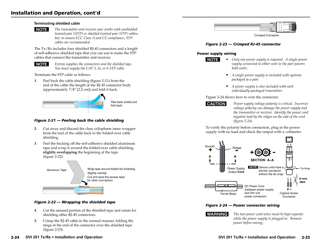
DVI 201 Tx, DVI 201 Rx specifications
Extron Electronics is known for its innovative solutions in the field of professional AV signal distribution and extension. Among its robust product lineup are the DVI 201 Rx and DVI 201 Tx devices, which are essential for transmitting and receiving digital video signals with exceptional performance and reliability.The Extron DVI 201 Tx is a DVI transmitter that seamlessly converts DVI signals to a format suitable for long-distance transmission. It features a DVI connector for input and utilizes advanced technologies to ensure minimal signal degradation. The DVI 201 Tx supports high-resolution video up to 1920x1200 at 60 Hz, making it ideal for high-definition applications, including presentations, video conferencing, and digital signage.
On the receiving end, the DVI 201 Rx is designed to receive the transmitted DVI signals and convert them back into a format ready for display. This device also supports resolutions up to 1920x1200 at 60 Hz, ensuring that users can enjoy crystal-clear image quality without loss of detail. The DVI 201 Rx features a straightforward installation process, allowing for plug-and-play functionality that reduces setup time and complexity.
Both the DVI 201 Tx and DVI 201 Rx employ Extron’s patented technology for signal integrity, which includes the use of equalization and error correction to maintain the reliability of the transmitted signals over longer distances. This aspect is crucial for installations that may involve several hundred feet of cabling, where conventional methods could lead to signal loss or corruption.
One of the key characteristics of both the DVI 201 Tx and DVI 201 Rx is their compatibility with a wide range of DVI-enabled devices. This versatility is particularly beneficial in diverse installation environments, such as corporate offices, classrooms, and control rooms, where different types of hardware may be in use.
Furthermore, both devices are designed with a compact form factor, allowing for easy placement in various setups, whether they are rack-mounted or positioned directly next to display devices. The robust construction and durable components ensure longevity and consistent performance over time, meeting the demands of professionals in the AV industry.
In summary, the Extron DVI 201 Rx and DVI 201 Tx are streamlined solutions for digital video signal transmission, showcasing innovative technology, high resolution support, and dependable performance, making them the preferred choice for AV professionals seeking quality and reliability.

