DVS 605 • Setup Guide
The Extron DVS 605 Digital Video Scalers are scaling products that allow most common signal formats to be processed, scaled, and output in any desired format. This setup guide allows an experienced user to easily and quickly set up and configure a
DVS 605 using step by step instructions. It covers how to perform basic operations using the front panel controls and selected Simple Instruction Set (SIS™) commands.
NOTE: | For full installation, configuration, menus, connector wiring, and operation details, see the DVS 605 User Guide, available at |
www.extron.com | |
Installation
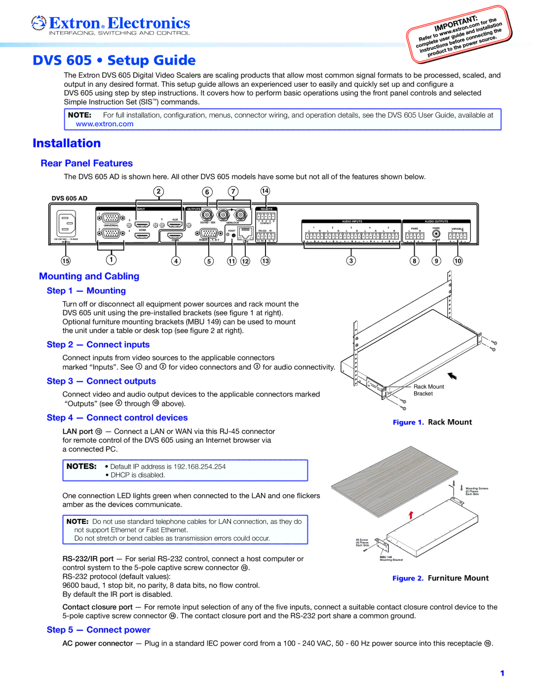
Rear Panel Features
The DVS 605 AD is shown here. All other DVS 605 models have some but not all of the features shown below.
DVS 605 AD |
|
| 2 |
| 6 | 7 |
|
|
|
|
|
|
|
| |
|
|
| INPUT |
| OUTPUTS |
|
|
| 1 |
|
|
|
|
|
|
|
| 3 | 5 | AUX | 3G/HD - SDI | GENLOCK |
|
|
| UNIVERSAL |
|
|
| ||
|
|
|
|
|
|
| |
| 2 | 4 | HDMI |
|
| RESET |
|
|
|
|
|
| |||
|
|
| HDMI |
| LAN | ||
50/60Hz |
|
|
|
|
|
| |
15 |
| 1 |
| 4 | 5 | 11 | 12 |
14 |
|
|
REMOTE |
|
|
1 2 3 4 5 | AUDIO INPUTS | AUDIO OUTPUTS |
CONTACT |
|
|
IR | 1 | R | 2 | R | L | 3 | L | 4 | L | 5 | L | FIXED | FIXED | VARIABLE | ||
L | L | R | R | R | R |
| L | R | ||||||||
Tx Rx G | G | S |
|
|
|
|
|
|
|
|
|
|
| S/PDIF |
|
|
13 | 3 | 8 | 9 | 10 |
Mounting and Cabling
Step 1 — Mounting
Turn off or disconnect all equipment power sources and rack mount the DVS 605 unit using the
Step 2 — Connect inputs
Connect inputs from video sources to the applicable connectors
marked “Inputs”. See A and B for video connectors and C for audio connectivity.
Step 3 — Connect outputs
Connect video and audio output devices to the applicable connectors marked “Outputs” (see D through J above).
![]()
![]()
![]()
![]()
![]()
![]() Rack Mount
Rack Mount ![]()
![]()
![]()
![]() Bracket
Bracket
Step 4 — Connect control devices | Figure 1. | Rack Mount |
|
LAN port L — Connect a LAN or WAN via this
NOTES: • Default IP address is 192.168.254.254 |
• DHCP is disabled. |
One connection LED lights green when connected to the LAN and one flickers amber as the devices communicate.
NOTE: Do not use standard telephone cables for LAN connection, as they do |
not support Ethernet or Fast Ethernet. |
Do not stretch or bend cables as transmission errors could occur. |
9600 baud, 1 stop bit, no parity, 8 data bits, no flow control. By default the IR port is disabled.
Mounting Screws
(2) Places
Each Side
#8 Screw
(4) Places
Each Side
MBU 149
Mounting Bracket
Figure 2. Furniture Mount
Contact closure port — For remote input selection of any of the five inputs, connect a suitable contact closure control device to the
Step 5 — Connect power
AC power connector — Plug in a standard IEC power cord from a 100 - 240 VAC, 50 - 60 Hz power source into this receptacle O.
1