Installation and Operation, cont’d

5.

Align the installed screws with the slots in the mounting


brackets, and place the unit against the surface, with the


screws through the bracket slots.

6.

Slide the unit slightly forward or back, then tighten all four


screws to fasten it in place.

Connections

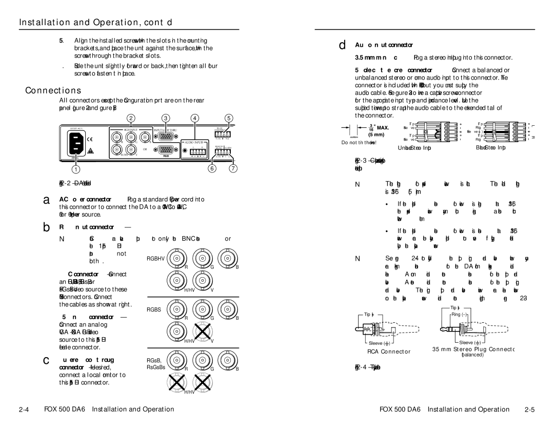
All connectors except the Configuration port are on the rear panel (figure 2-2 and figure 2-5).


2

3

4

5

100-240V 0.3A

RGB INPUT

INPUT LOOP THRU


RS-232


OVER FIBER

Tx Rx

NA

R

G

B

AUDIO INPUTS


L

R

REMOTE

ALARM


OR

RS-232


H/HV

V


RGB


Tx Rx

1 2

50/60 Hz


1

6

7


Figure 2-2 — DA’s connectors, left side


A

AC power connector — Plug a standard IEC power cord into


this connector to connect the DA to a 100 VAC to 240 VAC,


50 or 60 Hz power source.

B RGB Input connectors

NConnect an active input to only the BNC connectors or

the 15-pin HD


connector, not

RGBHV


both.


R

G

B


BNC connectors — Connect


an RGBHV, RGBS, RGsB, or


RsGsBs video source to these

H/HV

V


BNC connectors. Connect


the cables as shown at right.

RGBS


15-pin HD connector

R

G

B

Connect an analog


VGA - UXGA RGB video


source to this 15-pin HD

H/HV

V


female connector.


D Audio Input connectors —

3.5mm mini jack — Plug a stereo mini plug into this connector.

5-pole captive screw connector — Connect a balanced or unbalanced stereo or mono audio input to this connector. The connector is included with FOX 500, but you must supply the audio cable. See figure 2-3 to wire a captive screw connector for the appropriate input type and impedance level. Use the supplied tie-wrap to strap the audio cable to the extended tail of the connector.


Tip

Tip

L


Sleeve

Ring


Sleeve (s)


Tip

Tip

R


Sleeve

Ring

Do not tin the wires!


Unbalanced Stereo Input

Balanced Stereo Input


Figure 2-3 — Captive screw connector wiring for stereo audio input

NThe length of exposed wires is critical. The ideal length is 3/16” (5 mm).

If the stripped section of wire is longer than 3/16”, the exposed wires may touch, causing a short circuit between them.

If the stripped section of wire is shorter than 3/16”, wires can be easily pulled out even if tightly fastened by the captive screws.

NSee figure 2-4 to identify the tip, ring, and sleeve when you are making connections for the DA from existing audio cables. A mono audio connector consists of the tip and sleeve. A stereo audio connector consists of the tip, ring, and sleeve. The ring, tip, and sleeve wires are also shown on the captive screw audio connector diagram, figure 2-3.


Tip (+)

Tip (+)

Ring (-)

Sleeve ( )

Sleeve ( )

RCA Connector

3.5 mm Stereo Plug Connector

(balanced)

C Buffered Loop-through connector — If desired, connect a local monitor to this 15-pin HD connector.

RGsB,


RsGsBs

R

G

B


H/HV

V


Figure 2-4 — Typical audio connectors

2-4

FOX 500 DA6 • Installation and Operation

FOX 500 DA6 • Installation and Operation

2-5

Page 11
Image 11
Extron electronic FOX 500 DA6 user manual Installation and Operation, cont’d, Connections

FOX 500 DA6 specifications

The Extron FOX 500 DA6 is a state-of-the-art digital distribution amplifier designed to deliver exceptional performance for professional audio and video applications. This unit is particularly well-suited for environments where high-quality signal distribution is crucial, such as corporate settings, educational institutions, and control rooms.

One of the key features of the FOX 500 DA6 is its ability to distribute HDMI and multi-format video signals over long distances without compromising quality. The device supports resolutions up to 4K at 60 Hz, ensuring that users can leverage the latest high-definition video formats. This capability is especially important for modern digital signage and AV integration, where visual clarity is paramount.

The FOX 500 DA6 employs cutting-edge HDCP compliance, which simplifies content sharing across various devices while maintaining security protocols. This feature ensures that protected content can be distributed seamlessly, a fundamental requirement in many professional settings.

Another significant aspect of the FOX 500 DA6 is its flexible input and output configuration. The device comes with six outputs, allowing for multiple display connections without the need for additional hardware. This versatility makes the HDMI distribution amplifier ideal for scenarios where multiple monitors or projectors are in use.

In terms of ease of use, the unit is equipped with an intuitive user interface that simplifies setup and operation. It also supports automatic switching between inputs, a valuable feature for users who require quick transitions between sources. Technicians will appreciate the unit's ability to maintain signal integrity, with features like signal amplification and equalization that compensate for signal loss over longer cable runs.

The FOX 500 DA6 is designed for reliability and durability, meeting the rigorous standards expected in commercial environments. Its compact form factor allows for easy integration into racks or other setups without taking up excessive space.

Lastly, the Extron FOX 500 DA6 supports various control options, including RS-232 and TCP/IP, enabling seamless integration into existing control systems. Whether managing a large-scale AV system or a simple setup, this device offers the performance and flexibility necessary to meet diverse user needs.

In summary, the Extron FOX 500 DA6 is a powerful digital distribution amplifier that caters to the demands of modern AV applications with its advanced features, reliable performance, and user-friendly design.