Cabling the Enclosure
Bottom Panel Features
3
2
1
4
1
3 5
Figure 8. HSA 822 Enclosure Underside Connectors
A
![]() NOTE: All
NOTE: All ![]() the TIA/EIA T 568 A standard.
the TIA/EIA T 568 A standard.
BAC power connector — Connect this cord to the power source.
![]() NOTES: • For US domestic versions, this power cord is
NOTES: • For US domestic versions, this power cord is
permanently connected to the HSA. Connect the ![]() power cord to a 125 VAC, 60 Hz, 10 A power source.
power cord to a 125 VAC, 60 Hz, 10 A power source. ![]()
• For international versions, this power cord is a removable IEC power cord. Connect the cord to a
CCable access holes
DSpare AAP panel screws
ETop panel height adjustment screw — See “Adjusting the Height of the Top Surface” in the “Maintenance and Modifications” section.
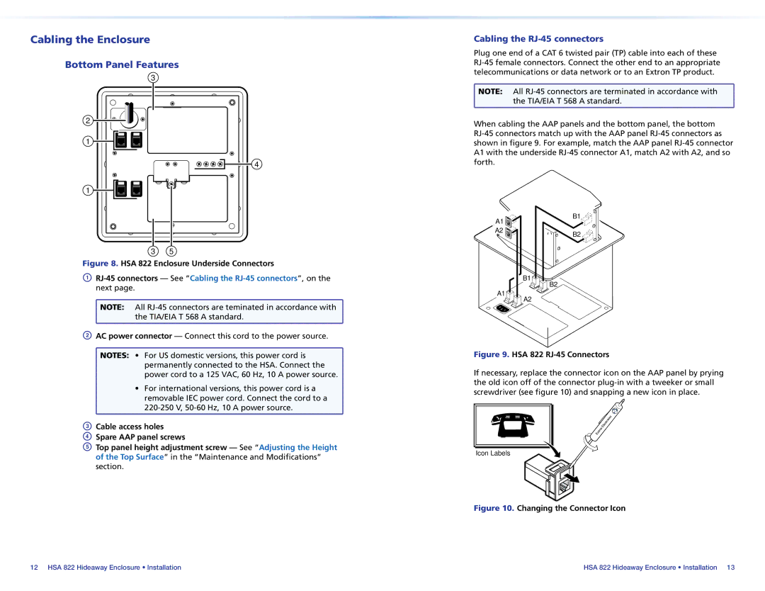
Cabling the RJ-45 connectors
Plug one end of a CAT 6 twisted pair (TP) cable into each of these
![]() NOTE: All
NOTE: All ![]() the TIA/EIA T 568 A standard.
the TIA/EIA T 568 A standard.
When cabling the AAP panels and the bottom panel, the bottom
A1 | B1 |
| |
A2 | B2 |
|
B1 ![]()
![]()
B2
A1 ![]()
![]() A2
A2
Figure 9. HSA 822 RJ-45 Connectors
If necessary, replace the connector icon on the AAP panel by prying the old icon off of the connector
Icon Labels
Figure 10. Changing the Connector Icon
12 HSA 822 Hideaway Enclosure • Installation | HSA 822 Hideaway Enclosure • Installation 13 |