IR 102 specifications
Extron Electronics is a well-known leader in the audiovisual industry, with a strong reputation for developing innovative and high-quality products. Two of their notable offerings are the IRL 20 and IR 102, which provide advanced infrared (IR) communication solutions for a wide range of applications.The Extron IRL 20 is an infrared lighting system designed to deliver high-performance IR signals for controlling AV devices. One of its primary features is its ability to provide reliable, long-range IR communication, which is essential in environments where line-of-sight control may be obstructed. The IRL 20 boasts a broad coverage area, ensuring consistent performance even in larger spaces. This capability is augmented by the system's dual IR emitters, allowing for enhanced signal strength and improved reliability.
Key technologies incorporated in the IRL 20 include a stable LED light source that ensures optimal performance across various distances. This innovation helps maintain signal integrity and minimizes potential interference from other electronic devices. Additionally, the IRL 20 is compatible with a range of Extron’s control processors, providing seamless integration into existing AV control systems.
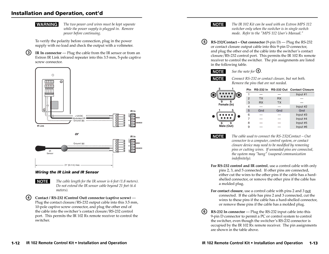
On the other hand, the Extron IR 102 serves as a versatile infrared receiver. It is equipped to decode incoming IR signals and transmit commands to connected devices, making it an essential component in any automated AV environment. The IR 102 features a streamlined design that can easily blend into any installation, promoting a clean and unobtrusive appearance.
Among the main characteristics of the IR 102 is its ability to support multiple IR codes, allowing users to control a variety of devices simultaneously. The unit's high sensitivity ensures it can pick up signals even when at a distance, enhancing the convenience of use. Moreover, both the IR 102 and IRL 20 have been designed with ease of installation in mind, featuring standard mounting options and simple wiring connections.
In summary, the Extron IRL 20 and IR 102 provide powerful solutions for infrared communication in audiovisual applications. Their advanced technologies, reliable performance, and compatibility with other Extron systems make them ideal for enhancing user experience in commercial and educational settings. With their focus on innovation, Extron continues to lead the way in the field of AV control solutions.

