Contents
Mini Power Amplifier
MPA 181T
User’s Manual
68-1082-01
Precautions
Extron’s Warranty
FCC Class A Notice
Safety Instructions English
Page
Quick Start Guide - MPA 181T
Step
MPA 181T Quick Start Guide QS-1
Attach the speakers to the MPA 181T
Table of Contents
Chapter 2 Installation and Operation
Appendix A Specifications, Part Numbers
MPA 181T Table of Contents
Table of Contents, cont’d
About this Manual About the MPA 181T Features
ii MPA 181T Table of Contents
Chapter1One
Features
Introduction
About this Manual
About the MPA 181T
Installation and Operation
Installation Overview Mounting the MPA 181T Rear Panel Features
Front Panel Features Setting up the MPA 181T Amplifier
Chapter2Two
Installation and Operation
Installation Overview
MPA 181T Installation and Operation
Mounting the MPA 181T
Installation and operation, cont’d
Under-desk mounting
Projector mounting
Figure 2-2 - Mounting the MPA 181T on the RSU shelf
Rear Panel Features
Power input
Figure 2-5 - Mounting the PMK
Figure 2-5 - MPA 181T back panel
Remote control
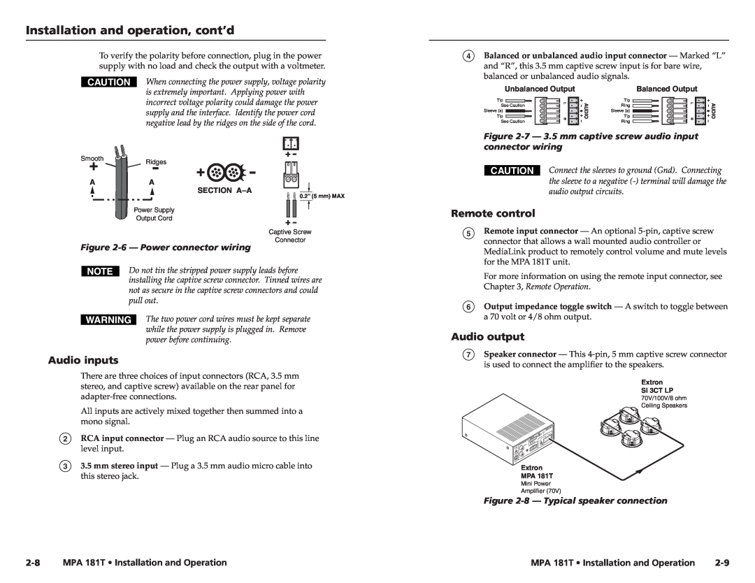
Figure 2-6 - Power connector wiring
Figure 2-7 - 3.5 mm captive screw audio input connector wiring
Audio inputs
Front Panel Features
Setting Up the MPA 181T Amplifier
Remote connector wiring
Figure 2-9 - Output speaker wiring
Remote Control Options
2-12 MPA 181T Installation and Operation
Figure 2-12 - Pinout diagram for a third party volume potentiometer
Chapter3Three
Specifications, Part Numbers, and Accessories
Remote Control Options
Specifications Included Parts Optional Accessories
Figure 3-1 - Three remote control options
Specifications, Part Numbers, and Accessories
Specifications
MPA 181T Specifications, Part Numbers, and Accessories
Audio
Optional Accessories
Accessories
Included Parts
Included parts
Specifications, Part Numbers, Accessories, cont’d
A-6 MPA 181T Specifications, Part Numbers, and Accessories