Installation and Operation, cont’d
Front panel features
D
E Audio
Making Connections
Power supply wiring
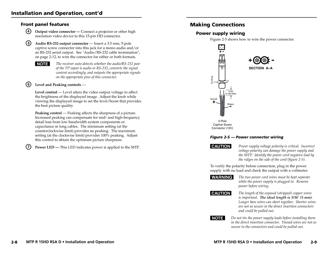
Figure 2-5 shows how to wire the power connector.
NThe receiver
F Level and Peaking controls —
WrapTie![]()
![]()
![]()
SECTION
Level control — Level alters the video output voltage to affect the brightness of the displayed image. Adjust the knob while viewing the displayed image to set the level/boost that provides the best picture quality.
Peaking control — Peaking affects the sharpness of a picture. Increased peaking can compensate for mid- and
G Power LED — This LED indicates power is applied to the MTP.
3/16”
(5 mm) Max.
Smooth
Ridges
Captive Screw
Connector (12V)
Figure 2-5 — Power connector wiring
CPower supply voltage polarity is critical. Incorrect voltage polarity can damage the power supply and the MTP. Identify the power cord negative lead by the ridges on the side of the cord (figure
To verify the polarity before connection, plug in the power supply with no load and check the output with a voltmeter.
WThe two power cord wires must be kept separate while the power supply is plugged in. Remove power before wiring.
CThe length of the exposed (stripped) copper wires is important. The ideal length is 3/16" (5 mm). Longer bare wires can short together. Shorter wires are not as secure in the direct insertion connectors and could be pulled out.
NDo not tin the power supply leads before installing them in the direct insertion connector. Tinned wires are not as
secure in the connectors and could be pulled out.
MTP R 15HD RSA D • Installation and Operation | MTP R 15HD RSA D • Installation and Operation |
