MTP R AV, MTP T AV specifications
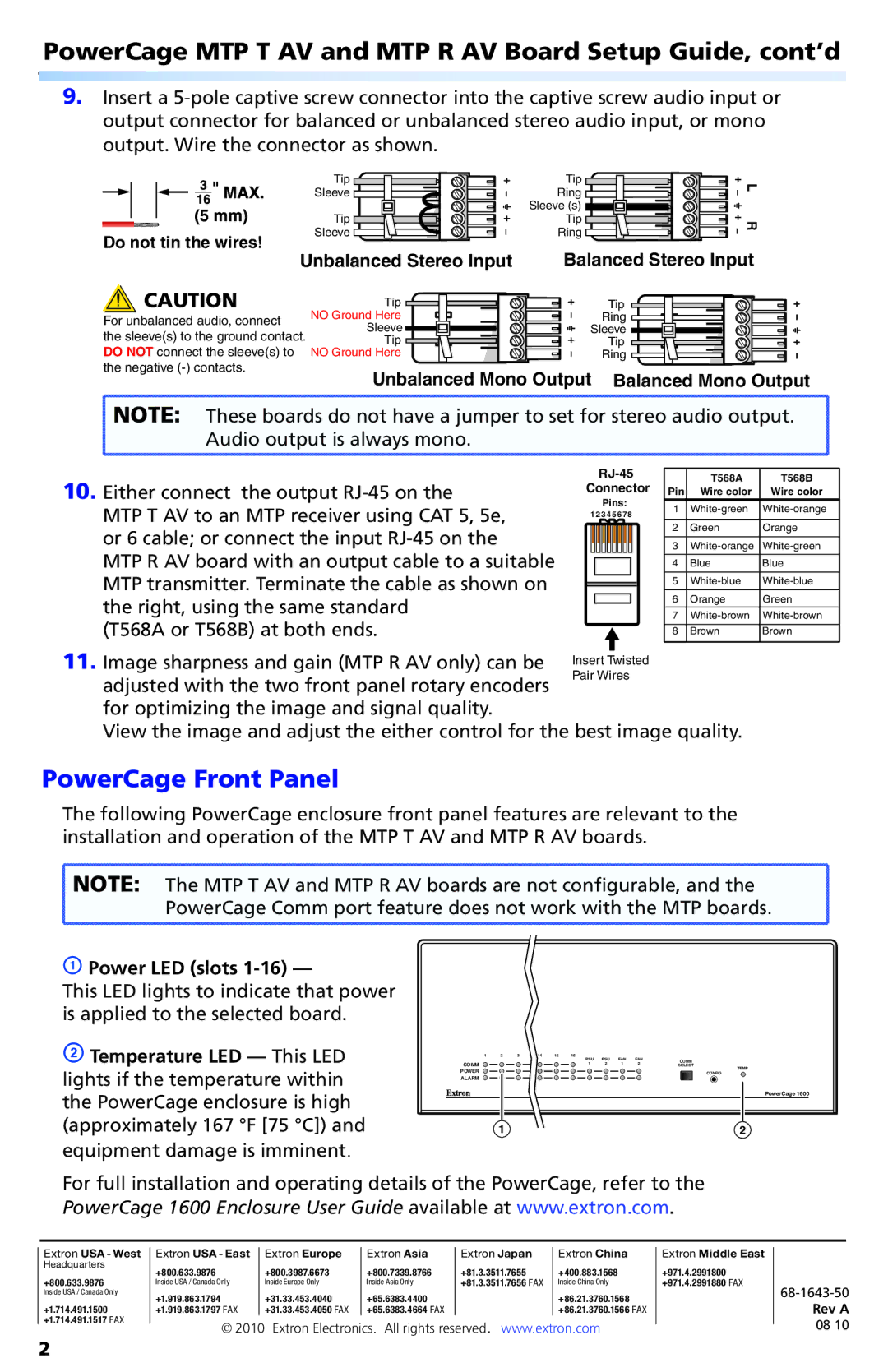
Extron Electronics has long been a prominent player in the AV distribution market, and their MTP T AV and MTP R AV series reflect their commitment to quality, innovation, and versatility. These devices are essential in extending audio and video signals over twisted pair cabling while maintaining exceptional performance.The MTP T AV, or the Master Transmitter, is designed to send high-quality AV signals such as composite video, S-video, and stereo audio over long distances using a single Category 5e or 6 cable. One of its key features is the support for resolutions up to 1080i, ensuring compatibility with a wide range of display technologies. It incorporates Extron's advanced transmission technology which minimizes noise interference, delivering a clean and reliable signal.
On the other hand, the MTP R AV acts as the Receiver, reconstituting the transmitted signals and making them ready for display. It features automatic input detection, simplifying the setup process and ensuring optimal performance based on the incoming signal. Like its counterpart, the MTP R AV also supports high-quality audio and video formats, making it a versatile choice for various setups.
Both the MTP T AV and MTP R AV utilize Extron’s patented Technology, which includes a built-in adaptive equalizer that automatically compensates for cable length. This ensures that even at the maximum distance, the signal quality remains intact. The devices also feature a robust locking mechanism for a secure connection, which is crucial in professional environments where reliability is paramount.
Another notable characteristic of these devices is their compact design, which allows for easy integration in racks or wall plates without occupying significant space. Their user-friendly interface and intuitive controls make installation and operation straightforward for AV professionals.
The MTP series is further enhanced by the ability to work with Extron’s extensive line of control systems, ensuring seamless integration into modern AV environments. Whether used for classrooms, conference rooms, or large-scale events, the MTP T AV and MTP R AV offer scalable solutions that cater to diverse AV distribution needs.
In summary, Extron's MTP T AV and MTP R AV represent the pinnacle of AV signal distribution technology. With their high-resolution support, adaptive equalization, and user-friendly design, these devices are ideal for a wide range of applications in the ever-evolving world of audiovisual technology.

