PPC 25 Installation Instructions
PPC 25 Overview
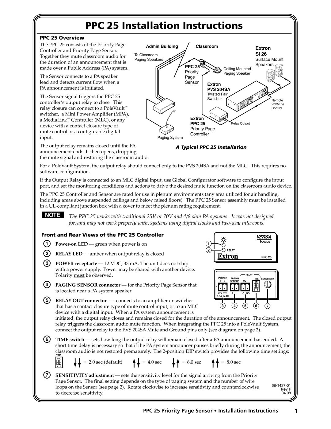
The PPC 25 consists of the Priority Page Controller and Priority Page Sensor. Together they mute classroom audio for the duration of an announcement that is made over a Public Address (PA) system.
The Sensor connects to a PA speaker lead and detects current flow when a PA announcement is initiated.
Admin Building | Classroom | |
To Classroom |
|
|
Paging Speakers |
|
|
| PPC 25 | Ceiling Mounted |
| Priority | |
| Paging Speaker | |
| Page | |
|
| |
| Sensor | Extron |
|
| |
|
| PVS 204SA |
Extron
SI 26
Surface Mount Speakers ![]()
The Sensor signal triggers the PPC 25 controller’s output relay to close. This relay closure can connect to a PoleVault™ switcher, a Mini Power Amplifier (MPA), a MediaLink™ Controller (MLC), or any device with a contact closure type of mute control or a configurable digital input.
The output relay remains closed until the PA announcement ends. It then opens, dropping
the mute signal and restoring the classroom audio.
Twisted Pair |
|
Switcher |
|
Extron |
|
PPC 25 | Relay Output |
Priority Page |
|
Controller |
|
Paging System |
|
A Typical PPC 25 Installation
Remote
Vol/Mute
Control
For a PoleVault System, the output relay should connect only to the PVS 204SA and not the MLC. This requires no software configuration.
If the Output Relay is connected to an MLC digital input, use Global Configurator software to configure the input port, and set the monitoring conditions and actions to drive the desired mute function on the classroom audio device.
The PPC 25 Controller and Sensor are rated for use in plenum environments (any area utilized for air handling, including areas above suspended ceilings and below raised floors). The PPC 25 Sensor assembly must be installed in a
The PPC 25 works with traditional 25V or 70V and 4/8 ohm PA systems. It was not designed for, and may not work properly with, systems using digital clocks and
Front and Rear Views of the PPC 25 Controller |
|
|
|
|
|
|
| |
A | 1 |
|
|
|
|
|
| |
2 | RELAY |
|
|
|
| |||
B | RELAY LED — amber when output relay is closed |
|
|
|
| |||
|
|
|
|
|
| PPC 25 | ||
C | POWER receptacle — 12 VDC, 33 mA. The unit does not ship |
|
|
|
|
|
|
|
| with a power supply. Power may be shared with another device. |
|
|
|
|
|
|
|
| Polarity must be observed. |
|
|
| RELAY |
|
|
|
|
| POWER | PAGING |
| TIME | SENSITIVITY | ||
|
|
| OUT | |||||
D | PAGING SENSOR connector — for the Priority Page Sensor that |
|
| SENSOR | ON |
| ||
|
|
|
|
|
|
| ||
| is located near a PA system speaker |
|
|
|
| 1 | 2 |
|
|
| 12V |
| C NO |
|
|
| |
E |
|
| 0.5A MAX |
|
|
|
|
|
RELAY OUT connector — connects to an amplifier or switcher |
|
|
|
|
|
|
| |
| that has a contact closure type of mute control input, or to an MLC |
| 3 | 4 | 5 |
| 6 | 7 |
| device with a digital input. When a PA system announcement is |
|
|
|
|
|
|
|
| initiated, the output relay closes and remains closed for the duration of the announcement. The closed output | |||||||
| relay triggers the classroom audio mute function. When integrating the PPC 25 into a PoleVault System, | |||||||
| connect the output relay to the PVS 204SA Mute and Ground pins only (see diagram on page 2). | |||||||
F | TIME switch — sets how long the output relay will remain closed after a PA announcement has ended. A | |||||||
| short time delay is necessary so that if the PA system announcer pauses briefly during the announcement, the | |||||||
| classroom audio is not restored prematurely. The | |||||||
TIME
ON
1 2
= 2.0 sec (default)
= 4.0 sec |
| = 6.0 sec |
| = 8.0 sec |
|
|
|
|
|
G | SENSITIVITY adjustment — sets the sensitivity level for the signal arriving from the Priority |
| Page Sensor. The final setting depends on the type of paging system and the number of wire |
| loops on the Sensor (see page 2). Rotate clockwise to increase sensitivity and counterclockwise |
| to decrease sensitivity. |
Rev F
04 08
PPC 25 Priority Page Sensor • Installation Instructions | 1 |